 |
|||
|
|
|||
|
Page Title:
Section {V. MAINTENANCE OF THE ELECTRONIC VOLTMETER ME-202(*)/U |
|
||
| ||||||||||
|
|
 TM 11-6625 -537-14-1
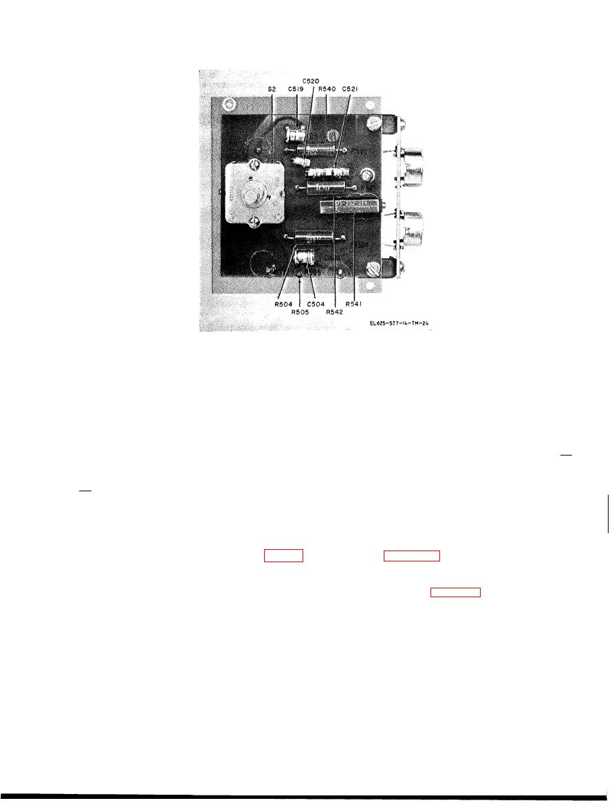
Figure 6-12. Ac range switch printed circuit board, showing component location.
Section {V. MAINTENANCE OF THE ELECTRONIC VOLTMETER ME-202(*)/U
RANGE
.
.
.
...500
6-8 l Fault Indication
NULL
.VTVM
The precision voltage divider is considered to be
AC-de
polarity
.
+
(positive)
faulty when differential voltage measurements
Voltage readout dials . . . . . . . . . . ..499.9 1 0
, , , ON (up position)
ON.
.
.
are out of tolerance on any range when the voltage
readout dials are set to any position other than 49
e. Allow at least 10 minutes warmup. Hold
99 1 0
at
switch
OPERATE-CALIBRATE
6-9. Equipment Required for Fault Isolation
C A L I B R A T E and adjust CALIBRATE control
to null VOLTS meter.
Fault isolation of the precision divider consists of
f. Measure the voltage across each resistor on
t a k i n g voltage readings across the resistors
within the divider. Use another electronic volt-
t h e precision voltage divider printed circuit
board. See figure 6-9 for component location. A
meter to make the measurements listed in table 6-
2.
faulty resistor is indicated if the voltage across
the resistor exceeds the maximum voltage dif-
6-10. Test Procedure
ference specified in table 6-2.
a. Remove two screws at the rear and slide the
6-11. General Parts Replacement Techniques
voltmeter from its case.
All parts of Electronic Voltmeter ME-202(*)/U
b. Remove four screws and separate the front
can be reached and replaced without special
panel from the chassis. Gently lay the front panel
procedures. Do not attempt to replace any of the
face down in front of the chassis.
precision w i r e w o u n d resistors with ordinary
CAUTION
power resistors, Nichrome resistors, carbon or
T h e card resistors on the precision
deposited carbon resistors, or metal film
voltage divider printed circuit board can
resistors. Use only approved components when
making repairs, After replacing components on
wire.
the printed circuit boards, coat any uncoated
c. Remove the cover from the precision voltage
areas around R305 through R31O on the reference
divider printed circuit board.
range resistor printed circuit board, and around
d. Set controls as follows:
6-17
|
|
Privacy Statement - Press Release - Copyright Information. - Contact Us |