 |
|||
|
|
|||
|
Page Title:
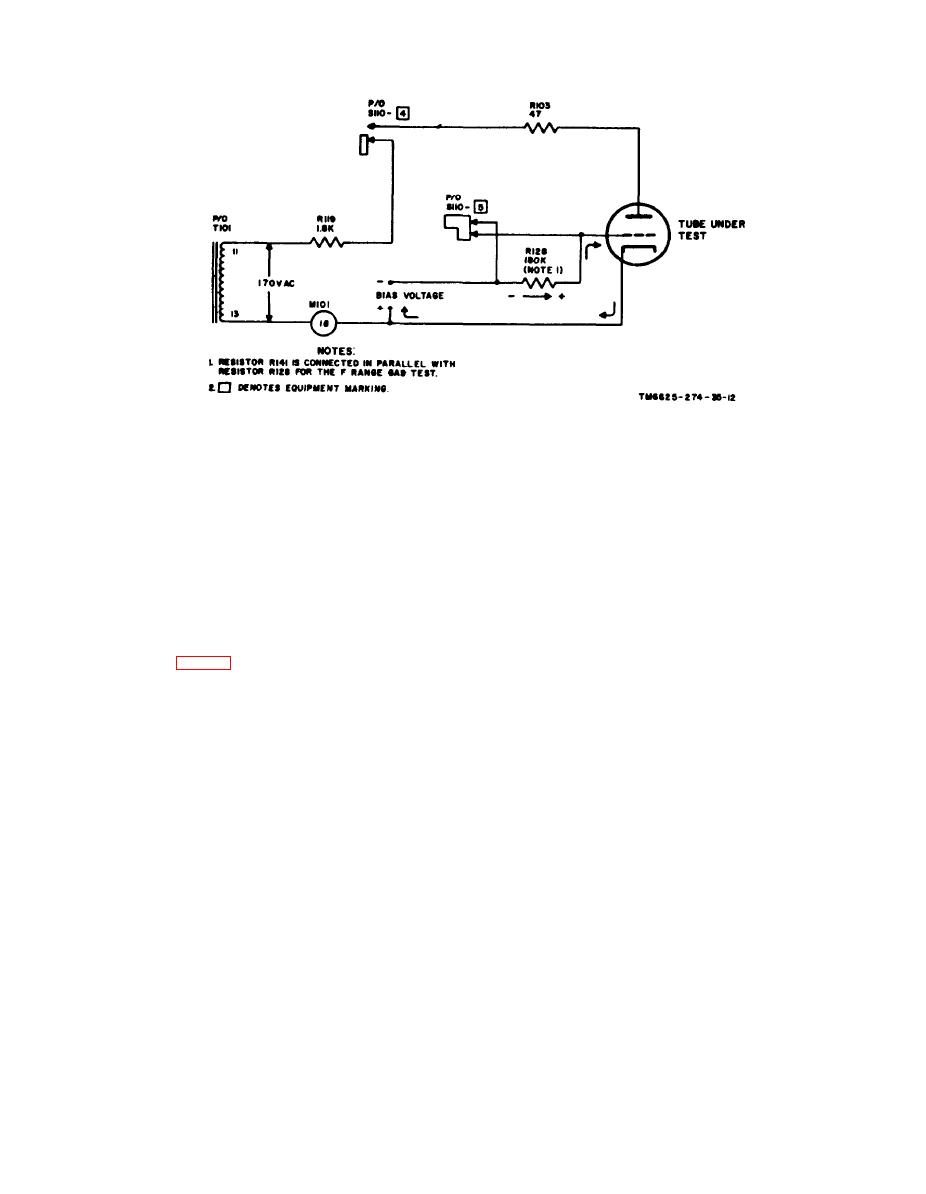
Figure 12. Simplified gas test circuit. |
|
||
| ||||||||||
|
|
 of the first four selectors have been
voltage drop across R128 will reduce the nega-
shown.
tive bias on the grid of the tube. and will cause
(a) The left FILAMENT selector is set
the plate current to increase. The increased
to apply voltage to pin 1 of the test
plate current must flow through M101 and will
sockets. This switch setting auto-
cause the meter reading to increase. The in-
matically breaks the conductor from
creased meter reading should not exceed one
p i n 1 at point A, and makes it
scale division.
Note. In the TV-7D/U, resistor R141 is connected
impossible for any other voltage to
parallel to R128 for gas tests when the RANGES F
reach pin 1 regardless of where the
position of the FUNCTION SWITCH is used.
succeeding selectors are set.
( b ) T h e right FILAMENT selector is
set to apply voltage to pin 2. The
conductor is broken from this pin
a. Selector Switches.
at point B, and no other voltage can
(1) T h e selector switches, FILAMENT
reach pin 2.
(S107 and S106), GRID (S105),
(c) When the GRID selector is set to
P L A T E (S104), SCREEN (S103),
deliver grid voltage to pin 3, the
CATHODE (S102), and SUPPRES-
conductor is broken from this pin
SOR (S101) are constructed and in-
at point C and the application of
terconnected so as to eliminate the
any other voltage to pin 3 is pre-
possibility of applying more than one
vented.
voltage to any tube pin at the same
( d ) Setting the PLATE selector to de-
time, or of creating a shorted con-
liver plate voltage to pin 4 breaks
dition by accidental disturbance of the
the conductor from pin 4 at point
switches. The basic principle of this
D.
interlocking circuit is shown in figure
(e) If the first four selectors are set in
13.
this manner, filament voltage is ap-
(2) Conductors from test socket contacts
plied across pins 1 and 2, grid
1 through 9 enter the switching cir-
voltage to pin 3, and plate voltage to
cuit from the left and progress toward
pin 4, but application of any other
t h e right through the FILAMENT,
voltage to these pins is impossible.
G R I D , PLATE, SCREEN, CATH-
ODE, and SUPPRESSOR selectors.
b. Shorts Test Switch. The operation of the
To simplify the figure, only portions
S H O R T S portion of FUNCTION SWITCH
|
|
Privacy Statement - Press Release - Copyright Information. - Contact Us |