 |
|||
|
|
|||
|
Page Title:
Mutual Conductance Test Circuit |
|
||
| ||||||||||
|
|
 supplies the screen grid voltage and the bias
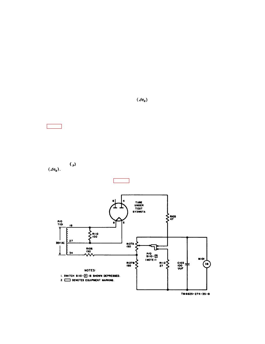
(4) When terminal 34 of T101 is negative
--
voltage to the tube under test for a direct mea-
with respect to terminal 19, the plate
surement of mutual conductance. The bias volt-
of the tube is negative with respect
age is adjusted by BIAS control R129. The
to the cathode and no plate current
signal voltage, developed across secondary No.
will flow. The damping action of the
3 of T101, produces an ac flow through voltage
meter movement results in a relatively
divider resistors R120 through R122. The volt-
constant meter indication even though
age across all three resistors is applied between
no current is supplied by the tube
the control grid and the cathode of the 6SK7
under test.
under test, and acts in series with the dc grid
e. Since the tube under test in this instance
bias. The signal voltage alternately swings the
is a duodiode, each half of the tube must be
grid voltage more negative or less negative,
tested separately. Whet the selector switches
thereby producing the variable grid voltage
are reset according to the information in the
required for a dynamic test.
tube test data book, the plate connection to pin
Note. Other electron tubes may require a smaller
4 is broken and pin 6 is connected into the test
signal voltage. When this is the case, switching cir-
circuit.
cuits enable only R120, or R120 and R121, to be con-
nected into the test circuit.
c. The mutual conductance test circuit is
actuated by pushbutton switch S110-3 (3 --
a. T h e mutual conductance (G m ) of an
MUT. COND.). The normal screen grid volt-
amplifier-type vacuum tube is an indication of
age of +130 volts dc is excessive for testing
the effectiveness of the tube to convert a small
certain tubes such as the 1R5. In such cases, it
change in grid voltage (grid signal) to a large
is necessary to hold down pushbutton switch
change in plate current, The mutual conduct-
S 1 1 0 - 2 ( 2 -- DIODE) before pushbutton
ance of a tube is found by dividing the change
switch S110-3 is depressed. This action breaks
by the change in grid
i n plate current
the connection between the screen grid of the
voltage
tube under test and contact A of resistor R130,
b. The plate voltage for the tube under test
and connects the screen grid to contact B of
is supplied by plate rectifier tube V101 (fig. 10
R130, which is at a potential of approximately
and 11). Screen and bias rectifier tube V102
+56 volts dc.
Figure 9. Simplified rectifier test circuit, TV-7D/U.
|
|
Privacy Statement - Press Release - Copyright Information. - Contact Us |