 |
|||
|
|
|||
|
|
|||
| ||||||||||
|
|
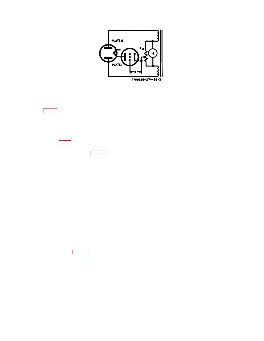
 Figure 5. Basic mutual conductance circuit.
Section Ill. CIRCUIT THEORY
produces a voltage drop across each resistor
6. Power Supply Circuits
with a polarity as shown in B, C, and D of
(fig. 3 and 42-44)
figure 3.
a. General. Input power to the primary of
(1) The bias voltage. applied to the tube
transformer T101 is supplied from a 105- to
under test, determined by the setting
125-volt ac, 50- to 1,000-cycles-per-second (cps)
indicated in the test data book, can be
p o w e r -source through FUSE lamp E103,
varied by rotating the BIAS control
POWER switch S111, and LINE ADJUST con-
knob on the front panel of the test
trol R126 (A, fig. 3). The LINE ADJUST con-
set. This relocates the tap on resistor
trol (a rheostat), operated in conjunction with
R129, thereby changing the difference
the line voltage test circuit (para 7), adjusts
in potential between the control grid
the voltage across the primary of transformer
and the cathode of the tube.
T101 to 93 volts ac.
(2) The normal screen grid voltage is
b. Plate Supply. Plate rectifier tube V101
+130 volts dc. If this voltage is too
is a type 83 mercury vapor rectifier tube con-
high for the tube under teat, a lower
nected in a full-wave rectifier circuit. Second-
screen grid voltage can be applied to
aries No. 1 and No. 2 supply approximately 154
the tube by depressing pushbutton 2
volts ac to the plates of the tube. Filament
-- DIODE. When pushbutton 2 --
voltage is supplied by 5-volt secondary No. 6.
DIODE is depressed, the screen grid is
The unfiltered, pulsating dc plate voltage output
disconnected from tap B on resistor
from the filament-cathode of tube V101 is
R130 and is connected to tap A. The
tapped off at the center tap of secondary No.
TV-7A/U, serial numbers 1 through
6. Secondary No. 2 is tapped at 20 volts to
1200, also uses voltage-dropping re-
supply voltage, through current limiting re-
sistor R133 (B, fig. 3) to reduce the
sistor R117, for emission tests on certain diode
screen grid voltage to a suitable value.
tubes.
c. Screen and Bias Supply. Secondary No.
(3) When the RANGES F position of the
4, 330 volts center tapped, supplies voltage to
FUNCTION SWITCH is used, vari-
the plates of screen and bias rectifier tube V102,
able resistor R139 is connected in
a type 5Y3WGTA (para 2b) rectifier tube,
parallel with R129, and R140 is con-
which is connected in a full-wave rectifier cir-
n e c t e d in series with R129. The
cuit. Filament voltage is supplied to V102 by
addition of R139 and R140 (D, fig. 3)
secondary No, 5. A voltage divider (B, C, or
reduces the current through the volt-
D, fig. 3) is connected between terminals 4 and
age divider. The voltage drop across
17 of T101. The voltage divider provides "bias
R130 is slightly decreased; the voltage
voltage for mutual conductance tests and screen
drop across BIAS control R129 is
grid voltage (when required) for the tube un-
greatly decreased, primarily due to
der test. When V102 conducts, current flow
adding a low resistance in parallel
through R129 and R130 (and R133 (B, fig. 3))
with the control.
|
|
Privacy Statement - Press Release - Copyright Information. - Contact Us |