 |
|||
|
|
|||
|
Page Title:
SECTION IX DEPOT OVERHAUL INSTRUCTIONS |
|
||
| ||||||||||
|
|
 T.O. 12P4-2APX-192
NAVAIR 16-35TS1843-1
SECTION IX DEPOT OVERHAUL INSTRUCTIONS
TM 11-6625-1646-25
Feed-thru insulator terminal (11)
9-1. GENERAL INFORMATION
12, 13
Generator assembly, AlAlA5 (15)
12 thru 19
End seal disc (26)
9-2. Refer to section I for transponder set test set description
Diode, AlAlAlCR1 (27)
and leading particulars.
Secondary radio frequency trans-
mission line (28)
9-3. SPECIAL TOOLS AND TEST EQUIPMENT.
Resistor, AlAlA1R1 (29)
Electrical contact (30)
9-4. Refer to section IV for special tools and test equipment.
Primary radio frequency trans-
mission line (31)
9-5. DISASSEMBLY.
Bushing insulator (32)
Connector (33)
9-6. This procedure provides instructions to gain access to the
Power coupler assembly, AlA1A2
radio frequency module, A1A1, components mounted on the
(34)
A1A1 module, and A1A1 subassemblies. After performing
Frequency coupler assembly,
steps 1 thru 8 in paragraph 9-7 to gain access to the A1A1
A1A1A3 (35)
module, perform only the required steps listed below to gain
Generator coupler assembly,
access to the desired subassembly or component.
A1AlA4 (36)
SUBASSEMBLY/COMPONENT
9-7. Perform disassembly as follows:
STEP NO.
(INDEX NUMBER)
1. Remove modules, A2 through A4, sides and top cover per
9
Frequency stub (2 and 3)
Stub support (4)
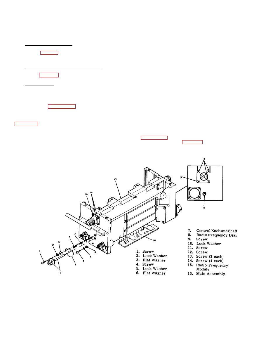
2. Remove screw (1, figure 9-1), lock washer (2), and flat
10, 11
Capacitor disc (9)
washer (3).
Disc insulator (10)
Figure 9-1. Radio Frequency Assembly (A1A1), Removal
9-1
|
|
Privacy Statement - Press Release - Copyright Information. - Contact Us |