 |
|||
|
|
|||
|
Page Title:
Table 8-3. Comparator-Decoder (A4), Troubleshooting (See figure FO-3) |
|
||
| ||||||||||
|
|
 T.O. 12P4-2APX-192
NAVAIR 16-35TS1843-1
TM 11-6625-1646-25
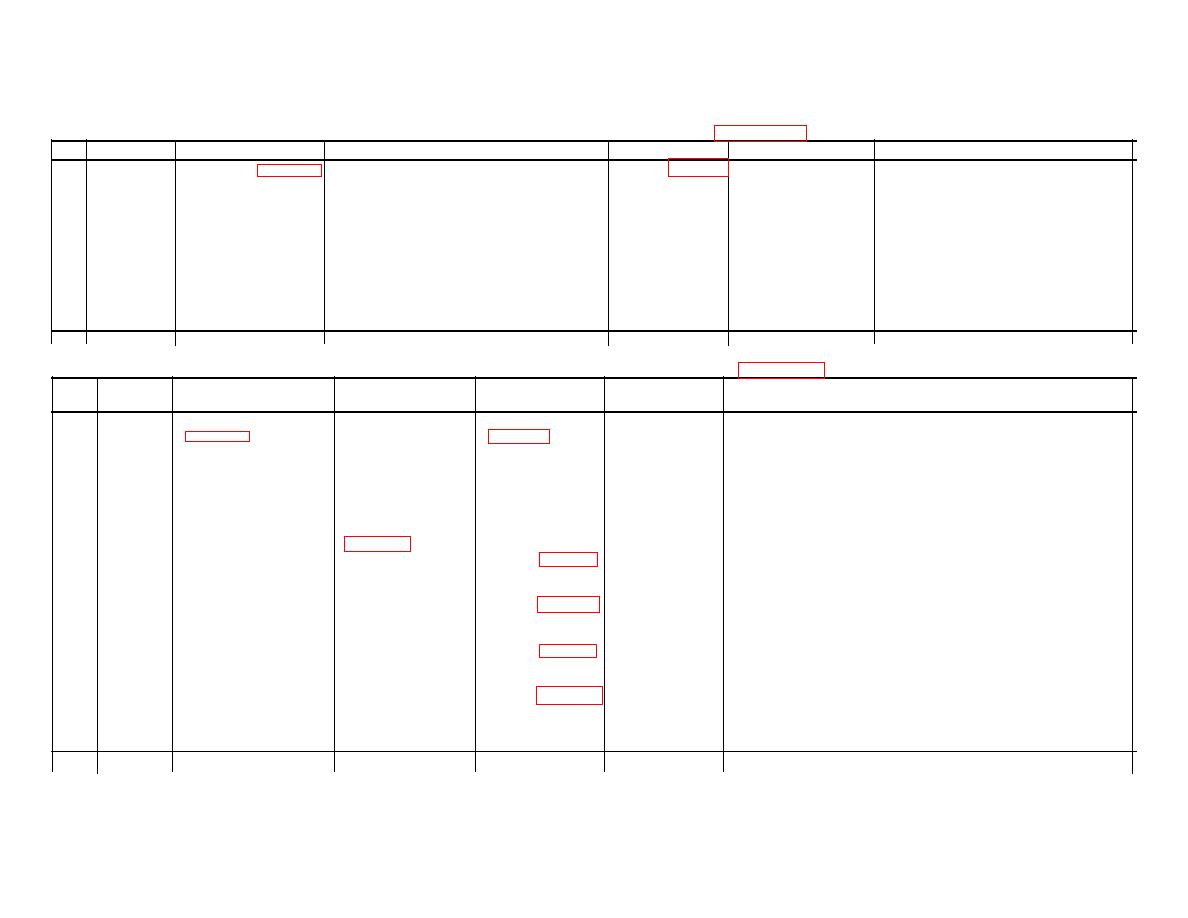
Table 8-2. Power Supply (A3), Troubleshooting (See figure FO-4)
Step
Test Point
Test Equipment
Control Settings and Instructions
Normal Indication If Indication Is Normal
If Indication Is Abnormal
1
TP1
Test set-up(figure 7-1)
Place RAD TEST- MON switch on C-6280
Refer to table 8-1. Proceed to step 2.
Check CR1, C1, and R1; replace
(4)
Voltmeter and A3
in MON position. Voltmeter on X10 range.
defective component(s)
extender board.
2
Emitter of
Same as step 1
Same as step 1.
Same as step 1.
Proceed to step 3.
Check Q1, Q2 and associated
Q1.
components; replace defective
(C)
component(s)
3
TP2
Same as step 1
Same as step 1.
Same as step 1.
Proceed to step 4.
Depot level maintenance required.
(5)
4
TP3
Same as step 1
Same as step 1.
Same as step 1.
Proceed with trouble
Check CR2, R4, and C3; replace
(6)
shooting procedures on defective component(s)
on A3 module.
Table 8-3. Comparator-Decoder (A4), Troubleshooting (See figure FO-3)
Test
Test
Control Settings
Normal
If Indication
Step
Point
Equipment
and Instructions
Indication
Is Normal
If Indication Is Abnormal
1
Collector
Test set-up
Set-up oscilloscope
Refer to
Proceed to
Check Q13, Q14, Q15, and associated components. Replace
of Q16.
(figure 7-1) and A4
for external triggering table 8-1.
Step 2.
Defective components(s)
(H)
extender board
place RAD TEST
MON switch on
C-6280 in MON
position. Set-up
AN/UPM-98A
controls per para-
graph 8-8, step 5.
2
Collector
Same as step 1
Same as step 1.
Refer to table 8-1.
Proceed to step Check Q9, Q10, Q11 and associated components. Replace
of Q12.
3.
defective component(s)
(I)
3
Collector
Same as step 1
Same as step 1.
Refer to table 8-1.
Proceed to step
Check Q1, Q2, Q3 and associated components. Replace defective
of Q4.
4.
component(s)
(J)
4
Base of
Same as step 1.
Same as step 1.
Refer to table 8-1.
Proceed to step
Replace A4 module. Depot level m aintenance required.
Q17.
5.
(K)
5
Collector
Same as step 1.
Same as step 1.
Refer to table 8-1.
Proceed with
Check Q5, Q6, Q7, Q8 and associated components. Replace
of Q8.
Routine trouble-
defective component(s).
(L)
ing procedures
on A4 module.
8-11
|
|
Privacy Statement - Press Release - Copyright Information. - Contact Us |
