 |
|||
|
|
|||
|
Page Title:
Troubleshooting Chart for Major Alarm Panel |
|
||
| ||||||||||
|
|
 TM11-5895-932-14&P
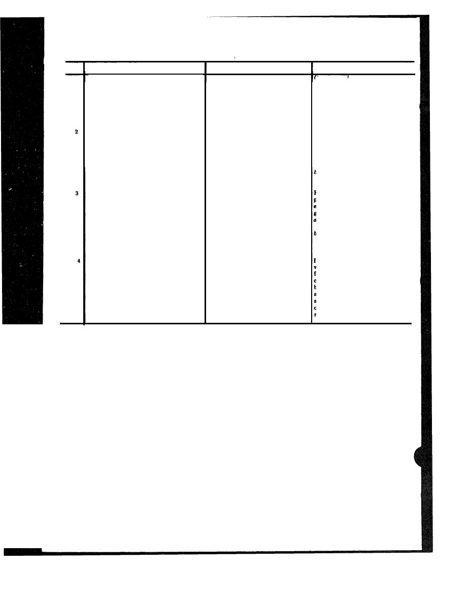
4-14. Troubleshooting Chart for Major Alarm Panel.
Item
Probable trouble
Trouble symptom
Check and corrective maintenance
(Continued)
will forward bias the diode in the
circuit, t h u s i n s u r i n g a v a l i d
VOM reading If continuity is
not obtained at either NC1 or
COM1. check associated diode
Refer to parts list, symbol CR1.
parts location
Defective lamp in switch
Audible tone from alarm converter
I Press switch SW1. All switches
without any lamp indication on
should glow red. Press switch
SW2 All switches should glow
alarm panels
amber If any switch fads to glow
in either color, replace associated
bulb
b If all switches fail to light. check
circuit breaker located on front
panel Reset if found deactivated
Gnd n o t b e i n g e x t e n d e d f r o m
Remove connector from back of alarm
Equipment is known to be in an
panel, locate pm associated with
alarm condition with no alarm
equipment to alarm panel.
equipment a l a r m a n d c h e c k f o r
indication given
ground
If ground is found, internal wiring
of alarm panel is defective
b If no ground is found, circuit trace
wiring back to IDF where ground
originates Use station drawing
showing the alarm wiring
Audible alarm interrupted only while
n order to check the switch coil, it
Switch is defective
will be necessary to remove the panel
switch is pressed
from the hay to gain access to the
component parts With the top and
bottom covers removed. a reading of
approximately 340 ohms across pins 4
and 5 indicates a good coil, while an
reading will require the
open
replacement of the switch
4-8
|
|
Privacy Statement - Press Release - Copyright Information. - Contact Us |