 |
|||
|
|
|||
|
Page Title:
Section IV. WIDEBAND CIRCUITS AND PATCH PANEL |
|
||
| ||||||||||
|
|
 TM 11-5895-878-14&P
Section IV. WIDEBAND CIRCUITS AND PATCH PANEL
2-12. Wideband Circuits, General
(3) The KG-24 is used to connect the
encrypted signals to clear text.
a. There are three locations where wideband
circuits may be accessed in the P&T. The black side of
circuits are accessed at five patch panels in bay 1.8 (fig.
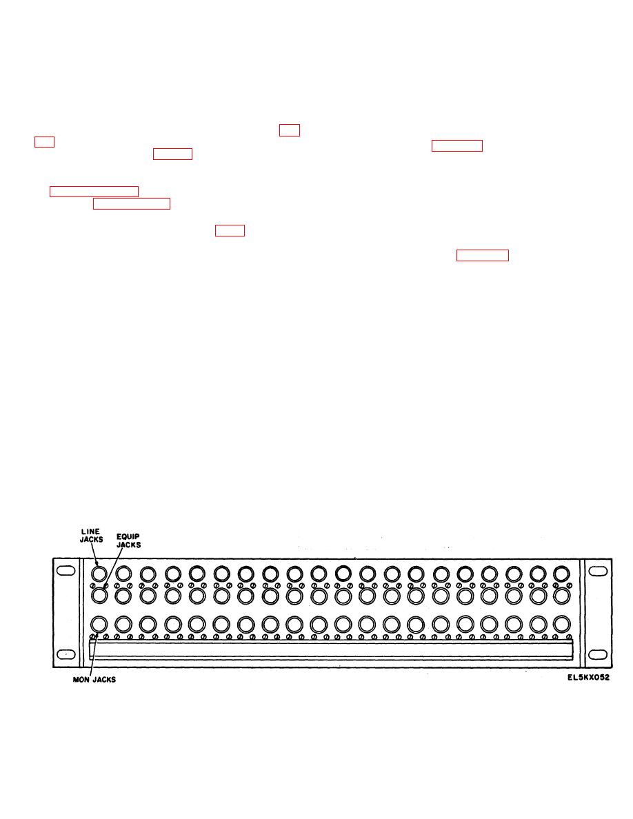
2-14. Wideband Patch Panel
patch panels in -bay 2.1 (fig. 1-8).
panel contains 20 sets of 3 associated 75-ohm Twinax
b. Wideband circuits may contain video signals or
jacks. Each jack set is used for one circuit (send or
vf group signals. A typical wideband circuit is discussed
receive). The send circuit jack set is usually on the left
in paragraph 2-13. The wideband patch panel is
of the receiver circuit jack set. The top row of jacks are
discussed in paragraph 2-14.
LINE jacks. The second row of jacks are EQUIP jacks.
The bottom row of jacks are MON jacks.
An
identification card holder strip is mounted across the
2-13. Typical Wideband Circuit (fig. FO-8)
bottom of the jack sets.
a. General. The cable connecting equipment to
the patch panels is 75-ohm Triax type cable. The patch
cable is connected to the EQUIP jack. When there is no
panels are 75-ohm Twinax type. Therefore, Triax-to-
plug in the EQUIP jack, closed contacts in the EQUIP
Twinax adapters are used to connect the Triax cables to
jack connect that jack in series with the LINE jack. The
the patch panels.
LINE jack is similar to the EQUIP jack and completes a
b. Send Circuit.
The send signals from the
through circuit to the line cable connector. When a plug
Pentagon user are in clear text, and connected to the
is inserted into the EQUIP jack the normal through
LINE jack of a jack set in red patch bay 2.18. The jack
circuit to the line connector is broken. The equipment
set is wired normal through the LINE and EQUIP jacks
cable is connected to the plug in the EQUIP jack and the
of the jack set. The signals out of the jack set are from
line cable is terminated across a 75-ohm resistor (the
the EQUIP jack and connected to the input of a KG-24
impedance of the cable). When a plug is inserted into
crypto equipment. The *output signals from the KG-24
the LINE jack, the normal through is also broken. The
are encrypted and connected to the EQUIP jack of a
line cable is connected to the plug in the LINE jack. The
jack set in black patch bay 1.8. The jack set is normal
equipment cable is terminated across the 75-ohm
through wired. The output from the LINE jack is
resistor. A MON jack. is parallel connected across the
connected to the commercial radio send input.
line cable connection, through two 560ohm isolation
c. Receive Circuit. The receive circuit is similar to
resistors and a 75-ohm termination resistor. The
the send circuit except for the following:
isolation. resistors provide a monitoring signal that is 30
(1) Signals are received from the commercial
dB below the line signal.
radio in a secure crypto form.
(2) Receive jack sets are used in both the
black and red patch bays.
Figure 2-37. Wide Band Patch Panel, Front View.
2-47
|
|
Privacy Statement - Press Release - Copyright Information. - Contact Us |
