 |
|||
|
|
|||
|
Page Title:
Section II. TYPICAL VF CIRCUIT AND PATCH PANEL |
|
||
| ||||||||||
|
|
 TM 11-5895-878-14&P
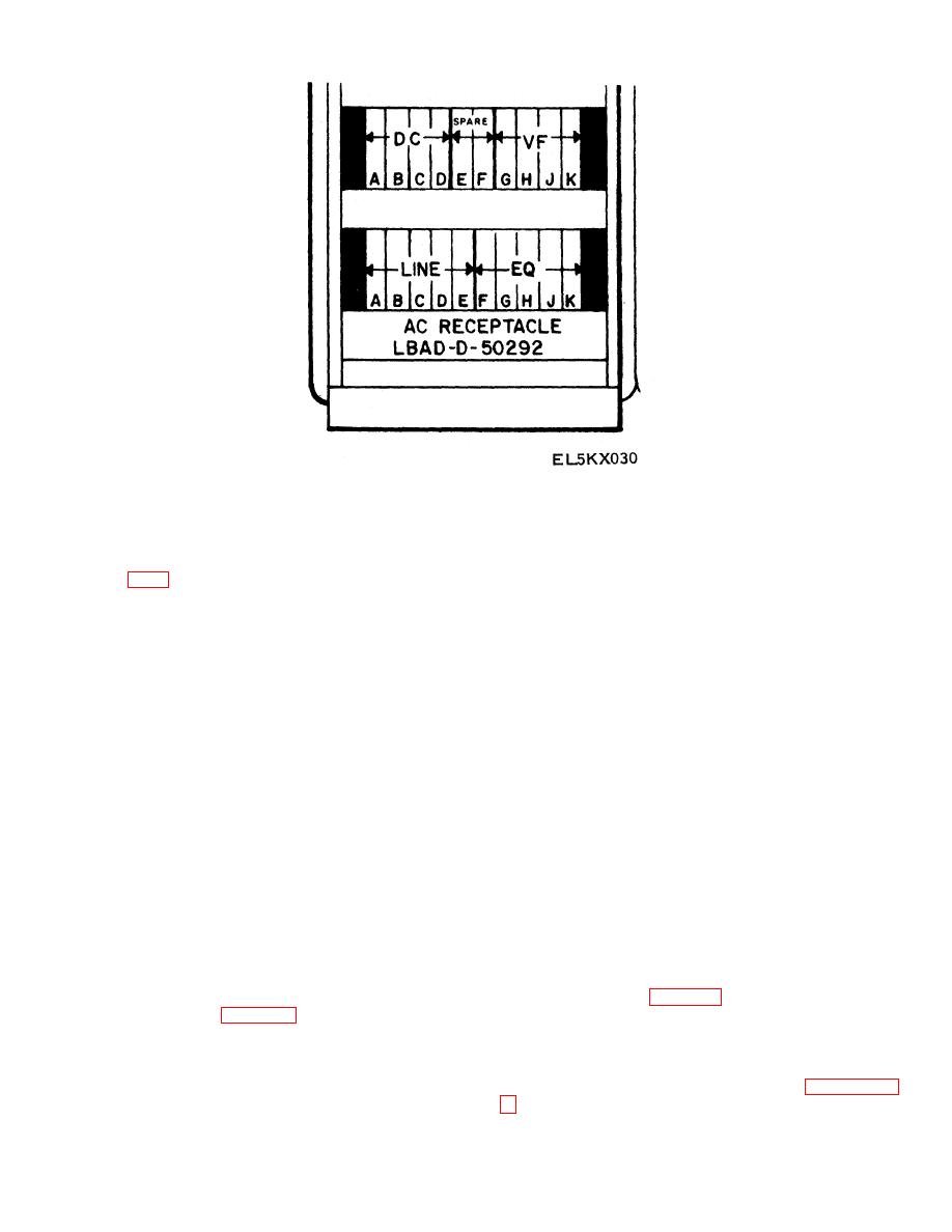
Figure 2-15. Special Intelligence Bay IDF, Front View.
Section II. TYPICAL VF CIRCUIT AND PATCH PANEL
module A on panel 1. Jacks 1 and 2 of module A, panel
2-4. Typical VF Circuit Connections
1 are cabled to the send side of the line vf equipment.
(fig. FO-3)
c. Receive Circuit. The receive circuit is similar to
a. General. The circuit is one that is typical to the
the transmit circuit, except the signals travel in the
P&T at the Pentagon. The box in the top left hand
opposite direction. The REC FROM VF EQUIP line, at
corner of the diagram represents line connections to the
the top of the diagram, is cabled to pins 3 and 4 of
telephone company or multiplex equipment. The box in
module A on panel 1. The second row of six jacks (7
the lower left hand corner, represents the equipment
through 12) of module A, panel 4 are cabled to the No. 2
side of the circuit. The circuit is a two-way (transmit and
set of jacks (REC) of patch panel No. 1 in bay 1.7.
receive) four-wire communications circuit.
These jacks are normal through wired to provide a
b. Transmit Circuit. The transmit circuit begins
complete circuit from jacks 1 and 2 to jacks 3 and 4 of
with the cable pair from the equipment at the bottom of
module A, panel 4. The receive side of the equipment
the diagram. The RECEIVE FROM pair is connected to
(SEND TO) pair is cabled from jacks 3 and 4 of module
pins 1 and 2 of connector J-1 on the rear of IDF panel 8
A, panel 8 to the receive side of the equipment. To
of bay 1.1. These two pins are connected to jacks 1 and
connect this circuit two dual-plug cross-connect patch
2 on cross-connect module A of panel 8. The pair for
cords are used at the IDF. One from jacks 3 and 4 of
RECEIVE FROM wires are cross-mounted from panel 8
module A, panel 1 to jack 1 and 2, row 2 of module A,
to jacks 3 and 4 of module A on panel 4, with a dual
panel 4. The second cross-connect patch cord, is
plug cross-connect patch cord. The first six jacks of
connected from jacks 3 and 4, row 2, module A, panel 4
module A on panel 4 are wired to jack set No. 1
to jacks 3 and 4, row 1, module A, panel 8.
(TRANS) of patch panel No. 1 in bay 1.7 as shown in
the diagram. The equipment jacks are connected to
2-5. VF Patch Panel
jacks 3 and 4 of crossconnect module A in panel 4 of
a. General. The VF patch panels are Lexington-
bay 1.1. The line jacks of the same patch. panel are
Blue Grass Army Depot (LBAD) D-33674 Two-Wire
connected to jacks 1 and 2 of the same cross-connect
Audio Patch Panels (fig. 2-16). Each patch panel has
module. The EQUIP and LINE patch panel jacks are
24 sets of four jacks. One set of jacks is used to access
wired normal-through (para 2-5).
This provides a
a two-wire circuit. When a four-wire circuit (transmit and
complete circuit from jacks 3 and 4 of module A panel 4
receive) is built, two sets of jacks are used. The
to jacks 1 and 2 of the same module. To complete the
description in b below covers the use of the panel in a
circuit to the line equipment, a second cross-connect
four-wire circuit similar to that discussed in paragraph 2-
dual plug,, 1 and 2 of patch cord is connected from
jacks 1 and 2 of module A, panel 4 to jacks 1 and 2 of
2-16
|
|
Privacy Statement - Press Release - Copyright Information. - Contact Us |
