 |
|||
|
|
|||
|
|
|||
| ||||||||||
|
|
 TM 11-5895-1012-10
d. In-Station Test. I n - s t a t i o n t e s t i n g i s a c -
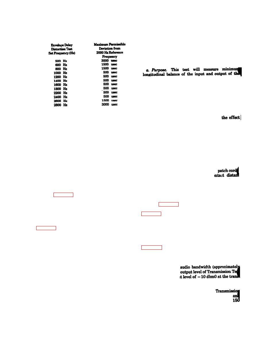
Table 6-1. Envelope Delay Measurements
complished in the same manner as station to station
testing except the local station acts as both trans-
mitter and receiver.
6-8. Minimum Longitudinal Balance Test
transmit and receive circuits and determine circuit
compliance with the standard operating requirements.
Any voltage that causes a current to flow in the same
direction in both conductors of a circuit is a
longitudinal voltage. This can be caused by extraneous
voltages induced into the circuit by either electro-
magnetic or capacitive coupling to both conductors
from other circuits, or as a result of any external
electrical disturbances. This test measures
a. Purpose. This test will measure maximum circuit
of the induced longitudinal voltage on the signal volt-
frequency change between stations or within a station
and determine compliance of circuits with the stand-
age by introducing a known signal voltage and measur-
ing the resulting longitudinal voltage.
ard operating requirements.
b. Test Equipment. The following test equipment is
b. Test Equipment. The following test equipment is
required to perform this test:
required to perform this test:
(1) Transmission Measuring Test Set (3 required).
(1) Noise Measuring Test Set.
center-tapped.
test).
(3) Resistors, 300 ohm 1%, 1 watt (2 required).
(3) Terminating plugs (600 ohms) and patch cords.
(4) Resistor, 150 ohm 1%. 1 watt.
c. Station-to-Station Teat. Contact distant station
and arrange for one station to act as transmitter and
(5) Terminating plugs (600 ohms) and
c. Station-to-Station Input Teat. Co
one as receiver. Perform the procedure below and then
station and arrange for one station to act as trans-
reverse roles and repeat the procedure.
(1) Transmitting Circuit. If the local station is to
mitter and one as receiver. Perform the procedure
act as transmitter, prepare the transmitting circuit
below and then reverse roles and repeat the procedure.
(1) Transmitting Circuit. If the local station is to
(a) 1000 Hz Test Tone Source set for - 10 dbm0
act as transmitter, prepare the transmitting circuit
coupled to transmit line.
shown in figure 6-5 and set the equipment as fellows:
(b) Frequency Counter set to measure ac within
(a) Transmission test sets jumpered as shown in
.1 Hz
(2) Receiving Circuit. If the local station is to act
(b) Patch panel impedance selectors at 600
as receiver, prepare the receiving circuit shown in
ohms.
(c) Patch panel frequency selector at less than 5
(a) Frequency Counter set to measure ac within
KHz.
.1 Hz.
(2) Receiving Circuit. If the local station is to act
(b) Noise Measuring Test Set set Hi Pass filter-
as receiver, prepare the receiving circuit shown in
ing and 600 ohm input.
(3) Procedure. The transmitting station will
(3) Procedure.
measure the Test Tone Source and record the
(a) At the transmitting station, set the fre-
indication to the nearest .1 Hz. The receiving station
quency of the Transmission Test Set No. 1 to a value
will measure and record the level meter indication on
near the top of the
the Noise Measuring Test Set. The receiving station
2700 Hz). Adjust the
will then observe the indication on the Frequency
Set No. 1 for an inpu
Meter for one minute and record this measurement.
mit input as read on Transmission Teat Set No. 3 volt-
The two stations will then compare the recorded fre-
meter. Note the level in volts and label this V1.
quencies and determine the difference between them.
(b) Adjust the range control of
(4) Performance Standard. The maximum
Test Set No. 2 voltmeter for a suitable sensitivity,
permissible change between the transmitted and
measure the low longitudinal signal across the
received frequencies is 5 Hz.
ohm resistor. Note this level and label it V2.
|
|
Privacy Statement - Press Release - Copyright Information. - Contact Us |
