 |
|||
|
|
|||
|
Page Title:
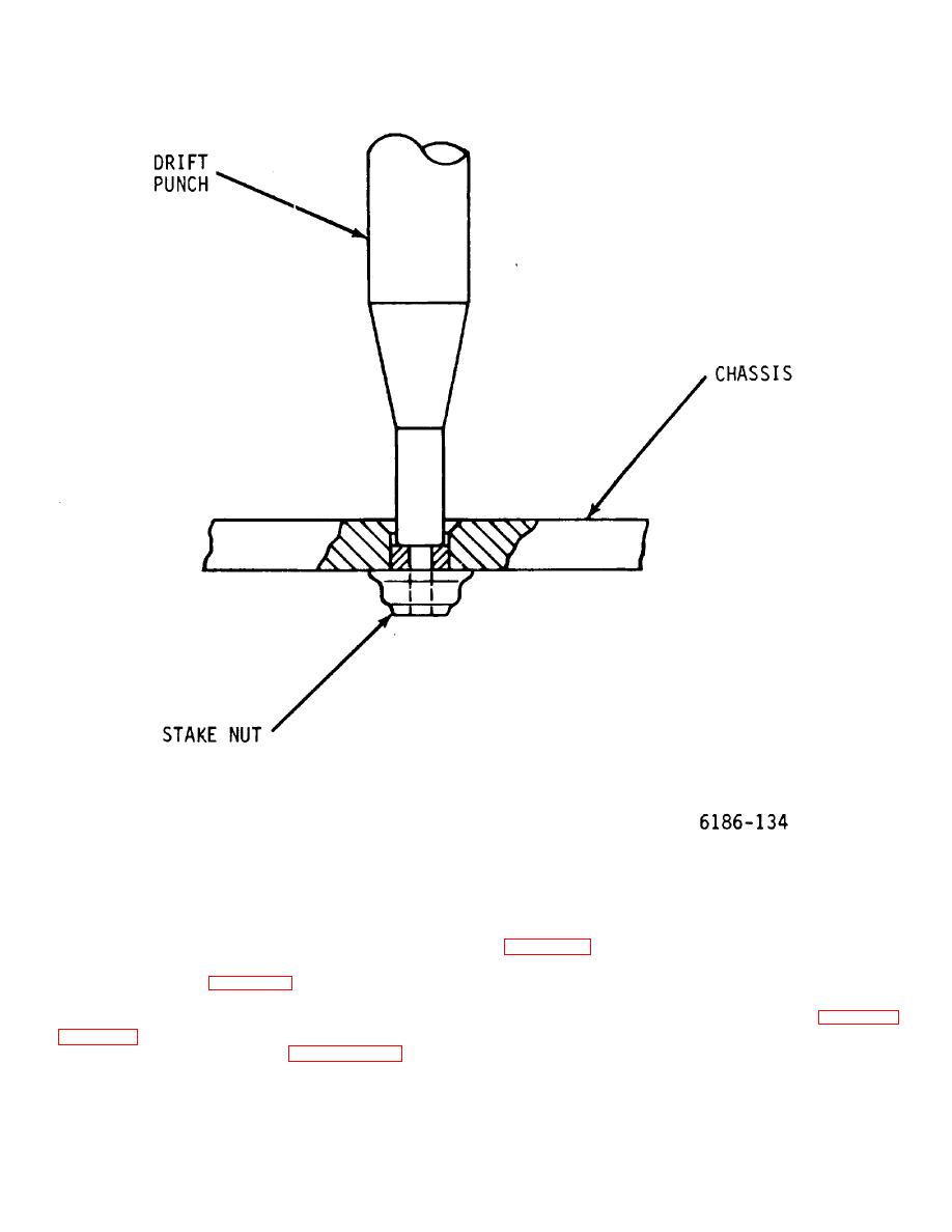
Figure 6-21. Stake Nut Removal Diagram |
|
||
| ||||||||||
|
|
 T.O. 31W2-2GSC24-2
TM 11-5805-688-14-1
NAVELEX 0967-LP-545-3010
Figure 6-21. Stake Nut Removal Diagram
slots.
6-76. BACKPLANE CONNECTOR PANEL REMOVAL
AND INSTALLATION.
To remove a backplane
2. Inside the card file, remove four screws
connector panel, perform the procedures in steps 1
through 9. Perform steps 10 through 12 to install a
screws securing top of card file to chassis, and 10
replacement panel in a chassis. Attaching hardware
screws securing left side of card file to chassis.
locations are shown in figure 6-25.
3. Remove rear connector panel and
disconnect cable assemblies as prescribed in paragraph
1. Remove printed circuit card access cover
6-28.
4
On rear of card file assembly, remove four
prescribed in steps1 through 4 in paragraph 6-22. When
screws on left side of chassis frame securing card file
cards are in card file and the cards are to be placed in
assembly to chassis.
the replacement card file, label each card with the proper
slot assignment from which the card was removed from
the card file to ensure that cards are placed in proper
6-59
|
|
Privacy Statement - Press Release - Copyright Information. - Contact Us |
