 |
|||
|
|
|||
|
Page Title:
Figure 6-9. Typical Performance Test Setup Diagram |
|
||
| ||||||||||
|
|
 T.O. 31W2-2GSC24-2
TM 11-5805-688-14-1
NAVELEX 0967-LP-545-3010
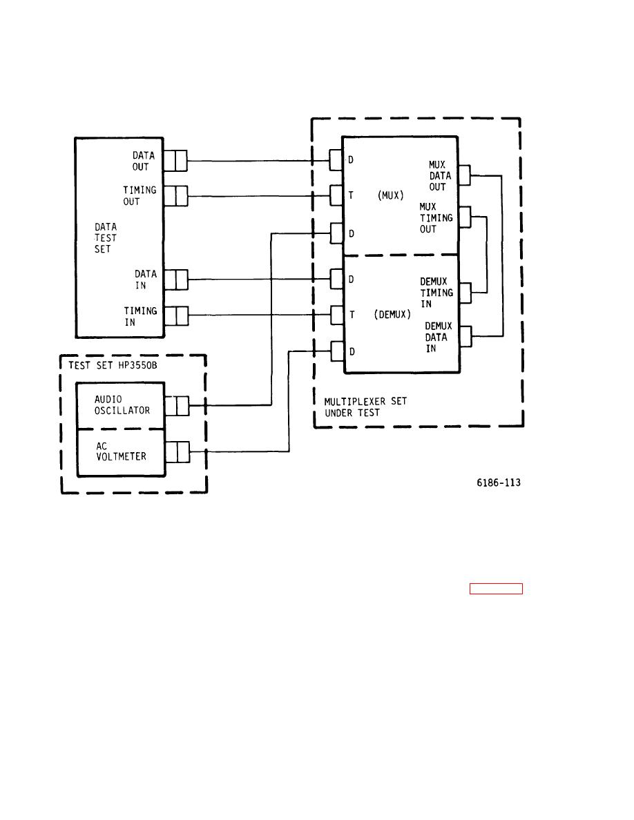
Figure 6-9. Typical Performance Test Setup Diagram
NOTE
At very low multiplexer output rates (Ro),
6. For the voice channel, involving a pair of VE
the time for initial frame synchronization by
and VD cards, to be tested (figure 6-9), connect audio
the demultiplexer may approach 6 minutes.
oscillator output to multiplexer channel D (data) input
Also, it may be necessary to momentarily
connector on the connector panel.
Connect the
press the DISPLAY RESET switch to
voltmeter input to the channel's demultiplexer D (data)
extinguish the LOSS OF FRAME B indicator
output.
following initial frame acquisition by the
demultiplexer.
6-38
|
|
Privacy Statement - Press Release - Copyright Information. - Contact Us |
