 |
|||
|
|
|||
|
Page Title:
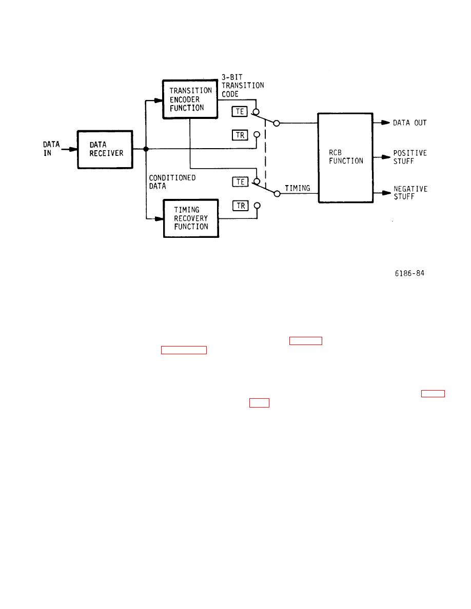
Figure 5-15. TE/TR Card - Simplified Block Diagram |
|
||
| ||||||||||
|
|
 T.O. 31W-2GSC24-2
TM 11-5805-688-14-1
NAVELEX 0967-LP-545-3011
Figure 5-15. TE/TR Card - Simplified Block Diagram
theory of operation discussions based on the TE/TR card
identifies the transition as having occurred during the first
logic diagram contained in the circuit diagrams manual.
half or the second half of an associated timing pulse, and
bit 3 indicates that the pulse transition is a positive going
or negative-going transition. The 3-bit code combinations
5-205. BLOCK DIAGRAM DISCUSSION.
are listed in table 5-1.
5-206. Transition Encoder Function (Figure 5-16).
5-208. Initially, the TE range switch is set to the switch
position that is equal to or higher than the incoming data
5-207. The transition encoder function receives the
bit rate. The switch selects one of the three bit rates
incoming data, without timing, that has a bit rate less
from divide-by-N counter No. 1, or one of the three bit
than 400 bps. The data receiver circuits condition the
rates from divide-by-N counter No. 2 as shown in figure
incoming data pulses to TTL levels that are compatible
with the digital circuits on the card. The transition
timing from the reference timer card and divides the
encoder circuits then monitor for the positive-going and
signals down to produce the 225-Hz, 450-Hz, and 900-
negative-going transitions of each incoming pulse.
Hz timing signals applied to the 75, 150, and 300-
When a pulse transition is detected, a 3-bit transition
positions of the TE range switch. Divide-by-N counter
code is generated and applied to the RCB function. The
No. 2 receives the 4800-Hz timing from the reference
3-bit transition code provides the following information:
timer card and divides the
bit 1 indicates that a pulse transition has occurred, bit 2
5-51
|
|
Privacy Statement - Press Release - Copyright Information. - Contact Us |
