 |
|||
|
|
|||
|
Page Title:
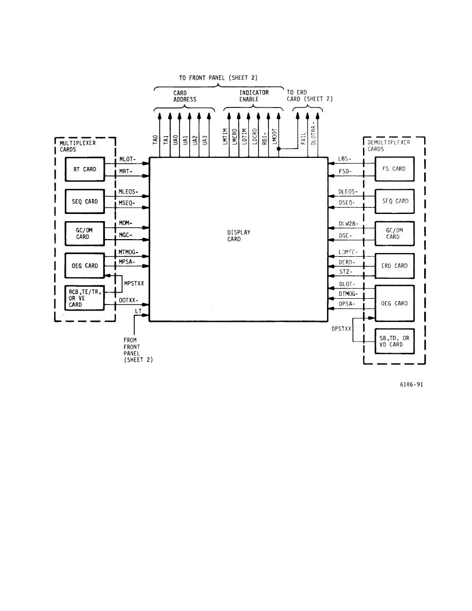
Figure 5-10. Diagnostic Overall System - Block Diagram (sheet 1 of 2) |
|
||
| ||||||||||
|
|
 T.O. 31W2-2GSC24-2
TM 11-5805-688-14-1
NAVELEX 0967-LP-545-3010
Figure 5-10. Diagnostic Overall System - Block Diagram (sheet 1 of 2)
the configuration is applied to the OEG card, which, in
panel. Signal LDTIM indicates that the system timing
turn, multiplexes the error signals into one positive stuff
from an external source to the demultiplexer is missing.
error signal that is applied to the display card as signal
The signal does not represent a local card error, and
DPSA-. 5-150. When demultiplexer loss-of-timing signal
therefore no card address is displayed on the FAULT
DLOT is generated from the OEG card to the display
LOCATION numerical display on the front panel. 5-151.
card, the display card, in turn, generates signal LDTIM
When diagnostic error signal LBS-, FSD-, DLEOS-,
that lights the LOSS OF DEMUX TIMING indicator on
DSEQ-, DLW28-, DGC-, LOMFC-, DERD-, DTMOG-, or
the front
DPSA from one of the common cards indicates
5-33
|
|
Privacy Statement - Press Release - Copyright Information. - Contact Us |
