 |
|||
|
|
|||
|
Page Title:
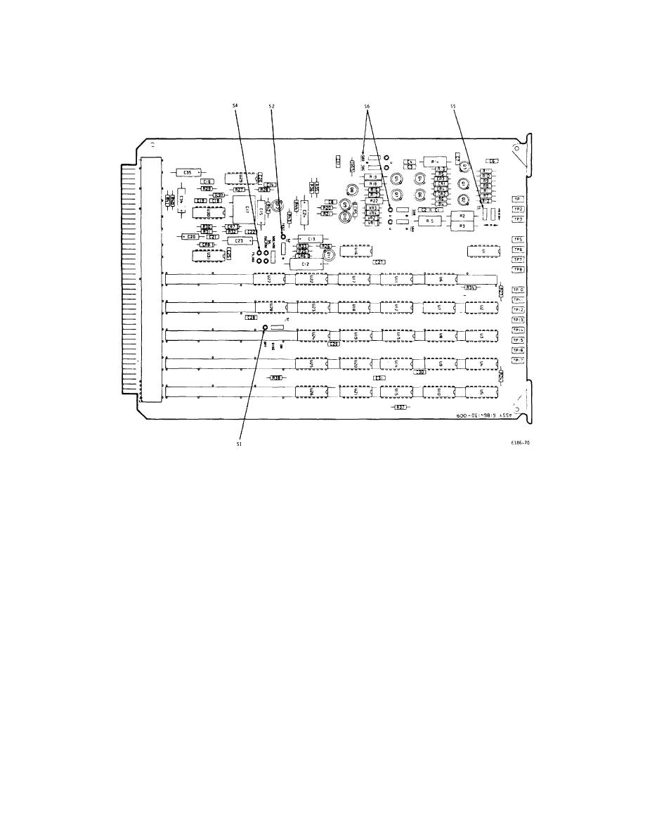
Figure 3-19. TD Card - Switch Location Diagram |
|
||
| ||||||||||
|
|
 T.O. 31W2-2GSC24-2
TM 11-5805-688-14-1
NAVELEX 0967-LP-545-3010
Figure 3-19. TD Card - Switch Location Diagram
the indicated N (normal) or R (reversed) position.
NOTE
4. Refer to the INTERFACE BAL, U75, or U6K block on
Setting S1 to the OFF position
the worksheet. If the INTERFACE BAL block is marked,
inhibits the display of errors detected
set S6A, S6B, S6C, and S6D to the B position. If the
by the TD diagnostic circuits.
INTERFACE U75 or U6K is marked, set the switches to
the U position.
2. Set S2 to the N (normal) position.
5. Multiply the number of ports (K) assigned to the
3. Refer to the DATA 0 N or R block on the worksheet,
channel on sheet
and
set
S5
to
3-51
|
|
Privacy Statement - Press Release - Copyright Information. - Contact Us |
