 |
|||
|
|
|||
|
Page Title:
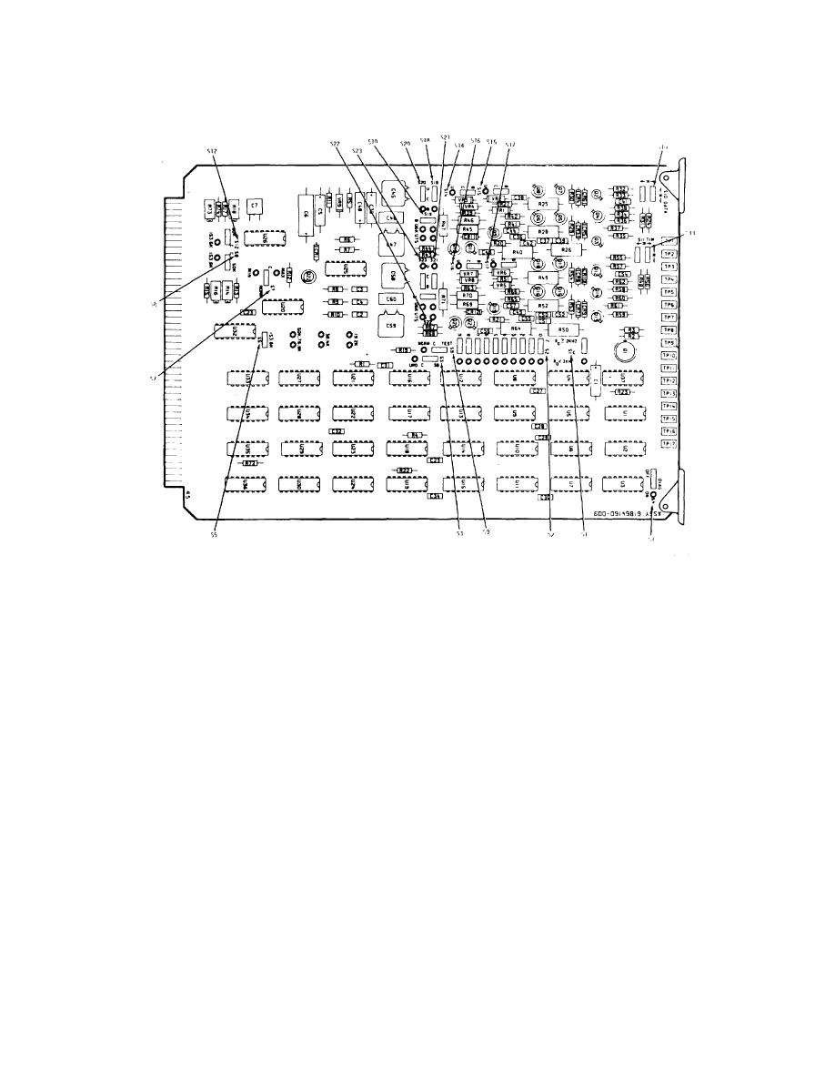
Figure 3-18. NBSB Card - Switch Location Diagram |
|
||
| ||||||||||
|
|
 T.O. 31W2-2GSC24-2
TM 11-5805-688-14-1
NAVELEX 0967-LP-545-3010
Figure 3-18. NBSB Card - Switch Location Diagram
value entered in the OUTPUT RATE (BPS) Rc block.
12. Refer to sheet 3 of the worksheets, and note in the
PORTS K blocks the number of ports (K) assigned to
9. Set S5 to the rate value shown.
each channel. Note the port rate (Rp) shown on sheet 4
of the worksheets. Multiply K and Rp, and compare this
10. If S5 was set to the 50K (50000 bps) position, set S8
value (KRp) with the channel's output data rate (Rc).
and S12 to the 50K position. If S5 was set to a position
13. If Rc is equal to KRp (Rc = KRp), set S3 to the SB
other than 50K, set S8 and S12 to the 153.6K position.
position, which completes the NBSB card setup process.
11.
Set
S7
to
the
NORM
(normal)
position.
Install the NBSB card in its appropriate card slot (1
through 15) in
3-49
|
|
Privacy Statement - Press Release - Copyright Information. - Contact Us |
