 |
|||
|
|
|||
|
Page Title:
Table 3-5. Reference Timer Setup Data |
|
||
| ||||||||||
|
|
 T.O. 31W2-2GSC24-2
TM 11-5805-688-14-1
NAVELEX 0967-LP-545-3010
in the OUTPUT RATE (Ro) BPS block of the TIMING
columns to the left of that column, on the same row, until
2n
section. The result of this computation must be of the
the column containing the installed oscillator's frequency
form (n = 0, 1, 2, 4 ...); otherwise, the input frequency
is reached. Set S6 on the RT card to the number of
columns counted. For example, assume that an Ro of
being supplied will not yield the desired Ro.
120, 000 bps (row 8, column 7) is desired and the RT
16. Locate the value computed in step 15 in the
card is fitted with an oscillator whose output frequency is
OSC FREQ/Ro column of table 3-5, and set S6 on the
1, 920, 000 Hz (row 8, column 3). Starting with column 7
RT card to the corresponding position indicated in the
and counting left through column 3 gives a count of 5 (7,
table. This completes the setup of an RT card operating
6, 5, 4, 3). The number 5 would then be set into S6 of
from an external reference timing source (S5 set to
the RT card. Proceed to step 13.
EXT).
11. Note the frequency of the oscillator installed
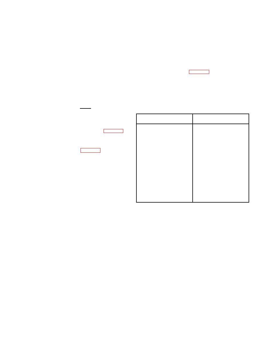
Table 3-5. Reference Timer Setup Data
on the RT card, and divide this frequency by the desired
n
Ro. The result of this computation must be of the form 2
(n = 0, 1, 2, 4 ....); otherwise, the desired Ro cannot be
obtained with the oscillator.
OSC FREQ/Ro
S6 Setting
12.
Locate the computed OSC FREQ/Ro
1
1
2
2
and set S6 on the RT card to the position indicated in the
4
3
table. For example, if the RT card oscillator frequency is
8
4
4, 800, 000 Hz, and the desired Ro is 600, 000 bps, then
16
5
OSC FREQ/Ro = 8. As shown in table 3-5, the proper
32
6
setting for S6 is position 4.
64
7
128
8
13. This completes the setup procedure for RT
256
9
cards operating from an internal timing source (S5 set to
512
10
INT). Install the RT card in slot 16 of the MULTIPLEXER
1024
11
row.
2048
12
4096
13
14. Set S4 to the 75 or 6K position as indicated in
8192
14
the INPUT INTFC 75 or 6K block on sheet 2 of the
16384
15
configuration worksheets.
32768
16
15. Determine the frequency of the external
timing source being supplied to the multiplexer from the
EXT FREQ HZ block on the worksheet, and divide this
frequency by the output rate (Ro) entered
3-40
|
|
Privacy Statement - Press Release - Copyright Information. - Contact Us |
