 |
|||
|
|
|||
|
Page Title:
DEMULTIPLEXER CHANNEL ELECTRONICS |
|
||
| ||||||||||
|
|
 T.O. 31W2-2GSC24-2
TM 11-5805-688-14-1
NAVELEX 0967-LP-545-3010
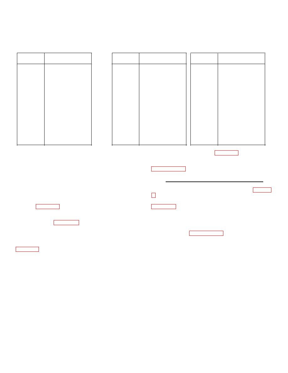
Table 3-3. Coarse Rate Conversion Strapping Data (Cont)
Fill
Card Strapping
Fill
Card Strapping
Fill
Card Strapping
Bits
0123456789
Bits
0123456789
Bits
0123456789
828
1111001111
842
1000011111
856
1000111111
829
1000101111
843
0100011111
857
0100111111
830
0100101111
844
1100011111
858
1100111111
831
1100101111
845
0010011111
859
0010111111
832
0010101111
846
1010011111
860
1010111111
833
1010101111
847
0110011111
861
0110111111
834
0110101111
848
1110011111
862
1110111111
835
1110101111
849
1001011111
863
1001111111
836
1001101111
850
0101011111
864
0101111111
837
0101101111
851
1101011111
865
1101111111
838
1101101111
852
0011011111
866
1011111111
839
1011101111
853
1011011111
867
0111111111
840
0111101111
854
0111011111
868
1111111111
841
1111101111
855
1111011111
3-39. The OUTPUT INTERFACE BAL block is marked
reflect the example shown in figure 3-4. The worksheet
with an X on the assumption that site cabling is
provides the information necessary to set up the
configured for balanced operation. Further, assuming
multiplexer common electronics section as prescribed in
that there are no phase reversals in the site interface
circuits or the transmission link, the OUTPUT DATA 0 N
and TIMING N blocks are each marked with an X,
3-41. DEMULTIPLEXER CHANNEL ELECTRONICS.
indicating normal. In normal operation, the positive-to-
3-42. Sheet 3 of the configuration worksheets (figure 3-
negative transition of the timing signal occurs in the
center of the data bit.
channel cards. As shown in the configuration example in
3-40. In figure 3-4, the multiplexer port sampling rate
Mbps; the value 1536000 is therefore entered in the
(Rp) is shown as 2.4 kbps; the value 2400 is therefore
INPUT RATE (Ro) BPS block. Next, the value 288000 is
entered in the PORT RATE (Rp) BPS block of the
entered in each of the OUTPUT RATE (BPS) (Rc) blocks
worksheet. Also, figure 3-4 shows a total port count,
for channels 1 through 5. Since all channel outputs are
including overhead (N + 1), of 20. The N value (19) is
the Type I form (paragraph 3-19), each channel's CARD
entered in the PORTS IN USE (N) block of the
TYPE SB block is marked with an X, indicating
worksheet.
The PORT STRAPPING blocks are
smoothing buffer. Output interfaces are assumed, for
completed to reflect the strapping assignments shown in
this example, to be balanced and without data or timing
phase reversals. Therefore, an X is entered in the
each marked with an X, indicating active, and PORT S
INTERFACE BAL, DATA N, and TIMING N blocks
blocks 2, 3, 4, 6 through 12, 14, 15, 16, and 18 are each
for each of the
marked with an X, indicating strapped. This completes
preparation of sheet 2 of the configuration worksheets to
3-19
|
|
Privacy Statement - Press Release - Copyright Information. - Contact Us |
