 |
|||
|
|
|||
|
Page Title:
Table 5-2. Performance Test for Power Supplies TF610.9-TF1927.7 Operating Voltages |
|
||
| ||||||||||
|
|
 T.O. 31W2-4-206-2
TM 11-5805-622-14/1
5-7. Tables 5-2 through 5-10 contain performance
tests for the Orderwire-Delay Equalizer Bay compo-
nents.
5-8. When performing the test procedures that fol-
low, care must be taken relative to dbm measure-
ments. As defined, dbm is a power ratio relative to
one milliwatt across a 600 ohm impedance. When
ture of 70F will not effect the performance of the
measuring voltage in db the impedance must be
equalizers.
known in order to convert to dbm. The db scales of
the W&G (Wandel and Golterman) test equipment
shown in figure 5-1, may be read directly only when
measuring across a 600 ohm impedance. For mea-
5-11. In order to test the overall performance of the
Delay Equalizers, the Envelope Delay Distortion of
surements across other impedances, corrections for
the W&G equipment may be calculated in accordance
the Cable Subsystem has to be measured by means of
the Delay Measuring Set LD-2 (W&G) from Interface
with instructions in the a--plicable manuals.
p
to Interface in both transmit directions as shown in
5-9. The Delay Equalizers in both terminals are de-
Cable Subsystem is inoperative (no traffice on any
signed to meet the amplitude and envelope delay dis-
tortion requirements of the entire cable subsystem
channels).
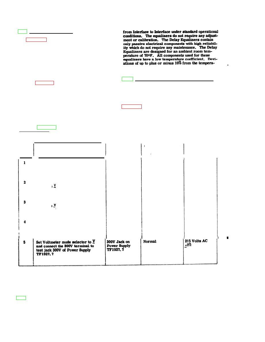
PRELIMINARY INSTRUCTIONS: 1. Use Siemens MSLDR830A for the following tests.
2. Connect test cord P-5741 to the range terminal on the Voltmeter.
CONTROL SETTING
PERFORMANCE
AND EQUIPMENT
POINT OF TEST
OPERATION OF TEST EQUIPMENT
STEP
STANDARD
OPERATION
+212 Volts DC
Anode Voltage
A on Power
Set Voltmeter mode selection switch
+2%
Supply TF610.9
to mA-/V- and connect the 300V
terminal to Jack A on Power Supply
TF610.9
20 volts AC +2%
Heater Voltage
H on Power
Set Voltmeter mode selection
Supply TF610.9
switch to and connect 30V termi-
n a l s to test jack H on Power Supply
TF610.9
20 volts AC
Normal
S1 on Power
Set Voltmeter mode selection
+10%
switch to and connect the 30V
Supply TF610.9
terminals to test jack S1 on Power
Supply TF610.9
24 Volts DC
Normal
Set Voltmeter mode selector to
S2 on Power
+15%
Supply TF610.9
mA-/V- and connect the 30V ter-
minals to the S2 test jack on the
Power Supply TF610.9
|
|
Privacy Statement - Press Release - Copyright Information. - Contact Us |
