 |
|||
|
|
|||
|
Page Title:
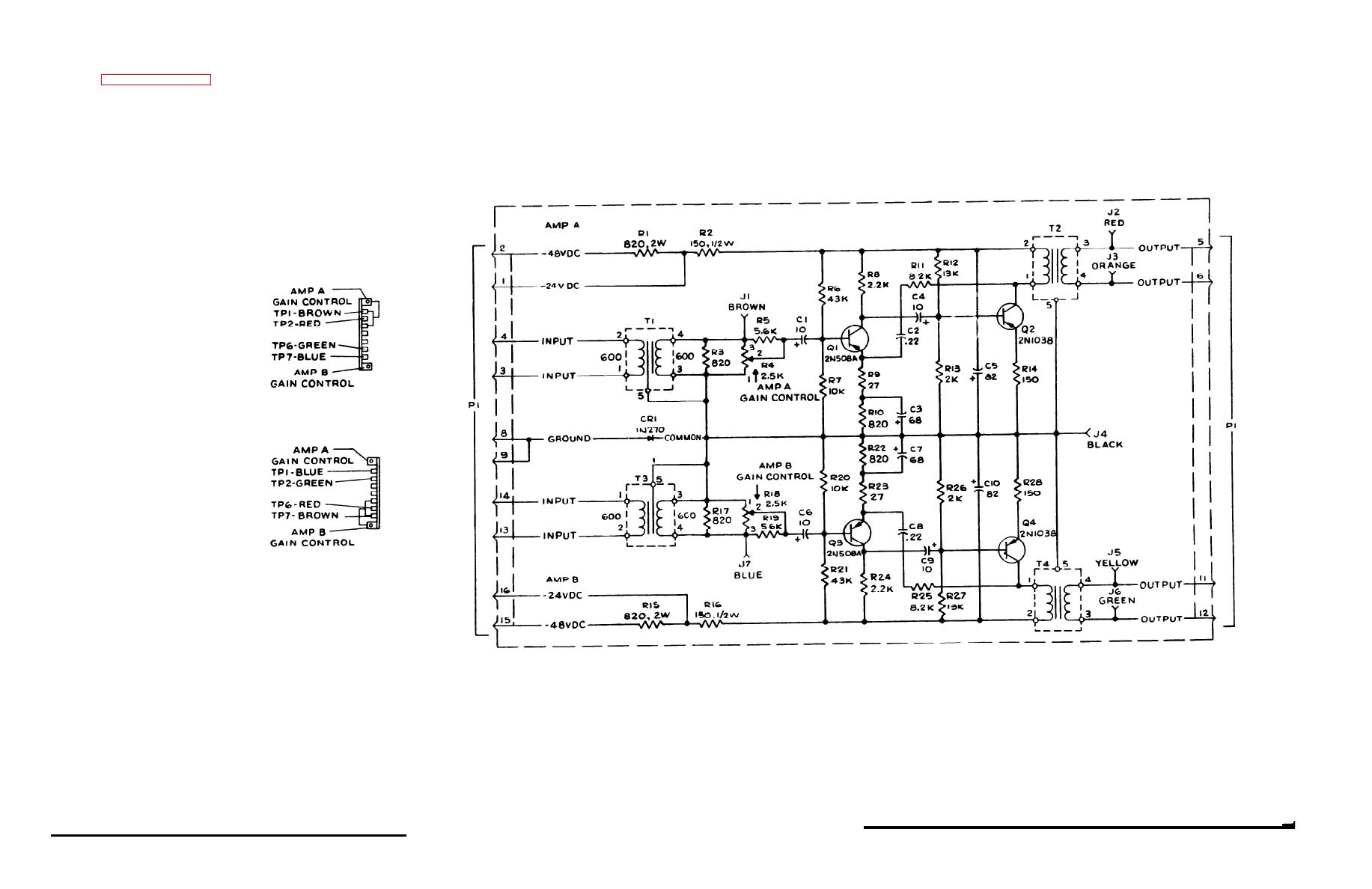
Figure 7-6. Voice-Frequency Amplifier Board, Schematic Diagram |
|
||
| ||||||||||
|
|
 TM
11-5805-451-15
NOTES:
1. UNLESS OTHERWISE SPECIFIED
ALL RESISTORS ARE IN OHMS, 5%
ALL CAPACITORS APE IN UF
2. SCHEMATIC DIAGRAM SHOWS AMP A,
AMP B ANO TP NUMBERS AND COLORS
IN FOLLOWING RACK POSITION
IN
THE FOLLOWING RACK POSITION
AMP A, AMP 8 AND TP NUMBERS
AND COLORS ARE AS INDICATED
PIN 1 ON CONNECTORS J1 THROUGH
J12 IS ALWAYS AT TOP OF RACK
Figure 7-6. Voice-Frequency Amplifier
Board, Schematic Diagram
|
|
Privacy Statement - Press Release - Copyright Information. - Contact Us |
