 |
|||
|
|
|||
|
Page Title:
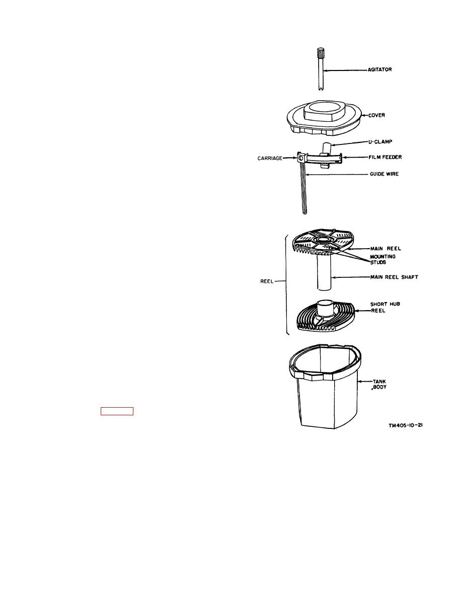
Figure 30.Photographic Processing Tank FM-3(1) |
|
||
| ||||||||||
|
|
 TM 11-405-10
(a) Compress the U-clamp on the film
feeder.
(b) Insert the end of the U-clamp into
the top of the main reel shaft. At the
same time, fit the two large holes in
the film feeder over the mounting
studs.
(c) Push the film feeder down as far as
it will go. The guide wire should rest
against the short curved edge of the
main reel and of the short hub reel.
(d) Release the U-clamp.
(3)
Place the assembled reel, with the short
hub reel on the bottom, on an even
surface.
(4)
Slide the carriage to either end of the rail.
(5)
In total darkness, insert the 4-inch width
(narrow width) of an exposed film into the
guide wire of the film feeder.
Note. The cut film is correctly positioned
for insertion into the assembled reel when
the notch in the edge of the film is in the
upper right-hand corner.
(6)
Lightly tap the edge of the film until it
drops completely into the slot.
Note. The film may be loaded with the
emulsion (dull) side in or out. However, to
avoid scratching the film, the film should
be loaded with the emulsion on the inside
of the curve formed by the grooves.
(7)
Move the carriage to the next notch and
slide in the next film.
(8)
Continue this loading process
((5)(7)
above) until all the exposed films are
loaded or until the capacity (12 cut films)
of the FM-8(1) is reached.
(9)
Remove the film feeder and place the
loaded reel in the tank body with the studs
toward the bottom.
(10)
Place the cover securely on the tank body,
turn on the room lights.
(11)
Check the temperature of the developer
solution (TM 11-401), start the continuous
timer (par. 23a or b), and pour the
developer solution into the tank body
through the hole in the center of the cover.
(12)
To agitate the developer solution (to
dislodge air bubbles that may be clinging
Figure 30.Photographic Processing Tank FM-3(1)
to the film), insert the agitator through the
hole in the cover. Engage it with the inner
cross member of the reel, then turn it
gently.
(13)
For stronger agitation, hold both pouring
ends and rock the entire unit.
AGO 5894A
38
|
|
Privacy Statement - Press Release - Copyright Information. - Contact Us |
