 |
|||
|
|
|||
|
Page Title:
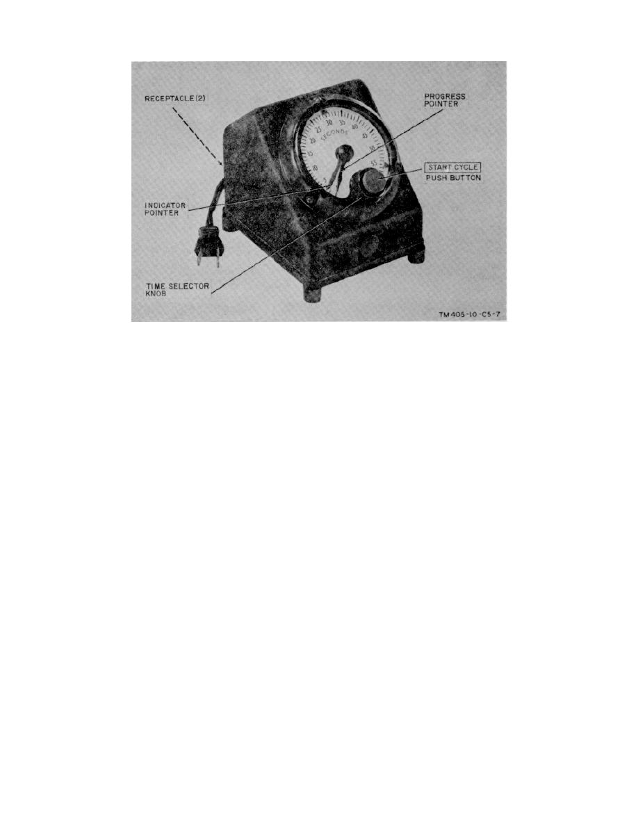
Figure 20.1. Interval Timer FN-5(2), front view. |
|
||
| ||||||||||
|
|
 Page 26, figure 20. Add figure 20.1 after 20.
Figure 20.1. Interval Timer FN-5(2), front view.
Paragraph 17. Make the following changes:
Subparagraph a (page 14 of C 3). Add "or
Subparagraph c(1), heading (page 14 of C 3). Change
EN-91B" to the heading.
"or EN-91A (fig. 2 and 3.1)" to EN-91A (fig. 2 and 3.1)
Subparagraph b(1l) (page 14 of C 3).
or EN-91B (fig. 3.2).
Change "or EN-91A" to EN-91A or EN-91B.
Page 27, paragraph 17. Make the following changes:
Paragraph 18.
Make the following
changes:
Subparagraph b(2).
Add subparagraph (2.1) after
Subparagraph a, line 3. Change "(par.
subparagraph (2).
26)" to (para 27).
(2.1) EN-91B.
Subparagraph a(3), heading (page 14 of C 3). Change
(a) Loosen the knurled screws (fig. 16.2) on the base of
"EN-91A" to EN-91A or EN-91B.
the variable condenser lens housing and lift off the upper
lamp house.
Subparagraph b, line 4. Change "(par.
(b) Open the access door and pull out the color filter
26)" to (para 27).
drawer.
Page 29, paragraph 18c. Make the following changes:
(c) Slide out the condenser lens assembly and insert a
Line 4. Change "(par. 26)" to (para 27).
replacement.
(Page 14 of C 3 and as changed by C 2, 26 Aug 63),
(d) Replace the color filter drawer and close the access
after the third sentence, add: Three rapid-shift and one
door.
4by 5-inch cut film negative carriers are supplied with the
EN-91B.
(e) Replace the upper lamp house and secure it with the
knurled screws.
Page 31, figure 25 (page 15 of C 3). Add figure 25.2
after figure 25.1.
figure
Interval Timer FN-5(2), front
view.
15
|
|
Privacy Statement - Press Release - Copyright Information. - Contact Us |