 |
|||
|
|
|||
|
|
|||
| ||||||||||
|
|
 TM 11-3895-200-14
5-11. DISASSEMBLY AND REASSEMBLY OF CLUTCH AND BRAKE ASSEMBLY - Continued
AF Remove the socket-head bolt (64), and then remove the lock bolt assembly (65), (66), and (67).
Remove the ball bearing (70) and latch spring (71), from the lower unit.
AG Disassemble the lock bolt assembly by removing the E-ring (65) and locknut (66) from the lock
bolt (67).
AH Remove the socket-head bolt (68) and the locking plate (69). Remove the ball bearing (70) and
the latch spring (71) from the upper unit.
A l Remove the two socket-head bolts and collar (73).
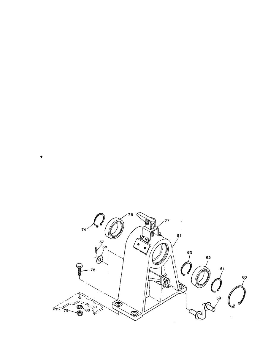
AJ Remove the hub locking device assembly (77).
AK Remove the retaining ring (61), and pull the reel drive shaft (76), with the retaining ring (63), ball
bearing (75), and retaining ring (74) attached, out of the drive bearing housing (81).
AL Remove the retaining ring (63) and slide the ball bearing (75) off the reel drive shaft (76).
AM Remove the retaining ring (74) from the reel drive shaft (76).
AN Remove the retaining ring (60) and shaft ball bearing (62) from the drive bearing housing (81 ).
AO Remove the four bolts (78), nuts (79), lock washers (80), and then remove the drive bearing
housing (81 ) from the frame.
REASSEMBLY
A Position the drive bearing housing (81) over the bolt holes in the frame and install the four bolts
(78), lock washers (80), and nuts (79).
B Insert the shaft ball bearing (62) into the drive bearing housing, and install the retaining ring (60).
C Install the retaining ring (74), ball bearing (75), and retaining ring (63) on the reel drive shaft (76).
D Insert the reel drive shaft and the attached ball bearing into the drive bearing housing, and
install the retaining ring (61).
E Install the hub locking device assembly (77) on the drive bearing housing.
5-15
|
|
Privacy Statement - Press Release - Copyright Information. - Contact Us |
