 |
|||
|
|
|||
|
Page Title:
Section II. VAP-AIR MODEL 26440001-01 |
|
||
| ||||||||||
|
|
 TB 9-2920-225-34-1
Section II. VAP-AIR MODEL 26440001-01
(5) If other readings are obtained, replace
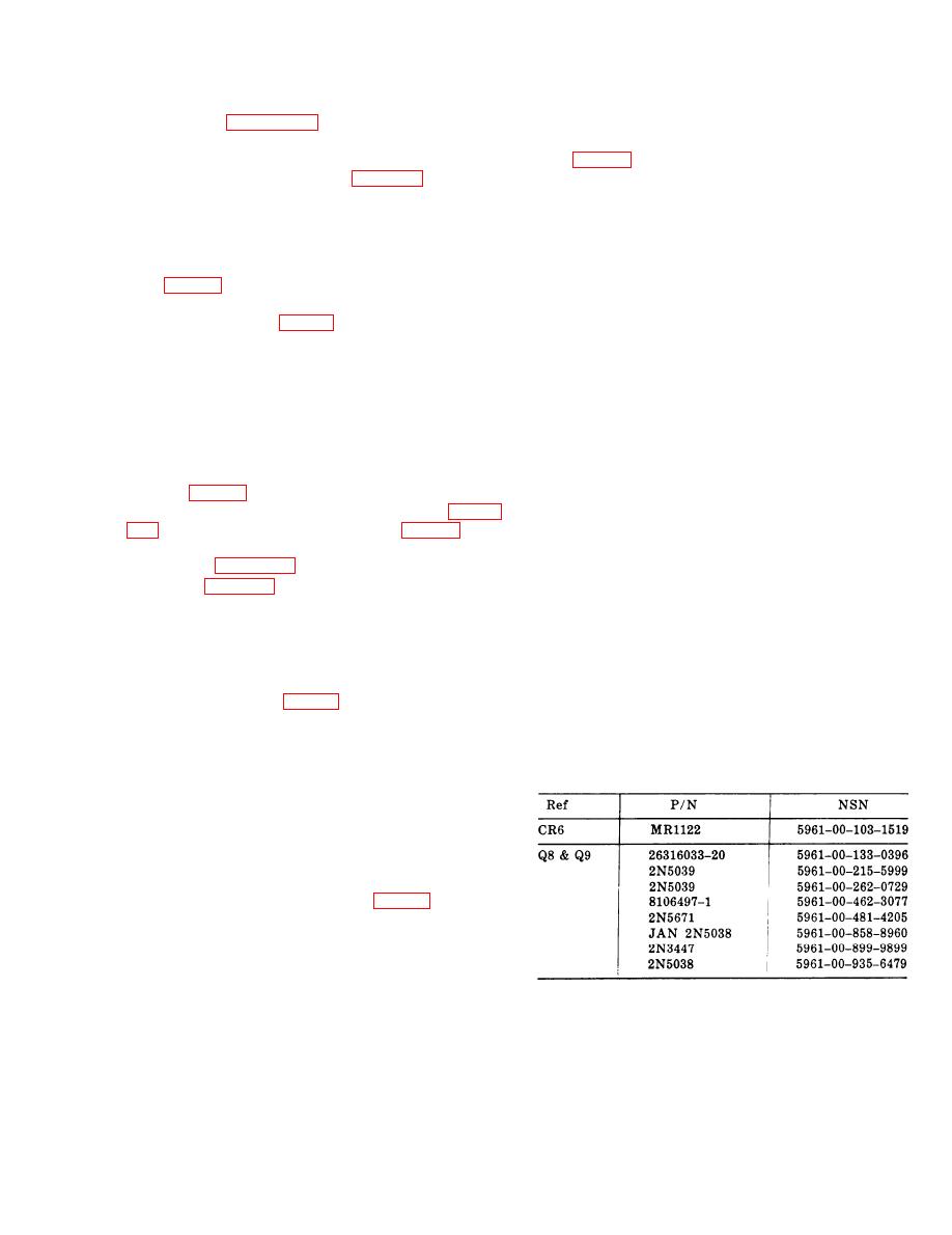
diode CR6 (MR1122), NSN 596100-1031519
of the regulator and its parts. Diode and transistor
(see fig. 2-4).
NSNS and parts numbers with substitute NSNS
and part numbers are listed in table 21.
(6) Reinstall transistor mounting plate.
d. Circuit Board. If no faulty components were
2-5. Checkout and Repair.
detected after performance tests a, b, and c above,
a. Voltage Adjustment Rheostat (R6) (power
replace the circuit board.
disconnected).
(1) Remove voltage adjustment access plug
e. Functional Check. Check the performance of
(see fig. 2-3).
the regulator on the test stand and make final
(2) Place ohmmeter test probes to terminals
voltage adjustments. Voltage output should read
of the rheostat (see fig. 2-3).
28 volts. If the regulator does not function prop-
(3) Rotate rheostat fully clockwise; reading
erly, perform the following:
should be less than 5 ohms.
(1) Check wires and connections.
(4) Rotate rheostat fully counterclockwise;
(2) Replace circuit board.
reading should be approximately 2500 ohms.
(3) Perform bench test procedures.
(5) If other readings are obtained, replace
rheostat.
NOTE
b. Transistors.
(1) Carefully remove transistors Q7, Q8, and
After final repair, check regulator on
Q9 (see fig. 2-3).
the test stand.
(2) Position transistor as shown in figure
If the regulator still does not function correctly
(3) If resistance values differ from the values
it will be necessary, if local skills permit, to test
shown in figure 22, replace the transistor ac-
each component. All the parts should be checked
cording to table 21.
with an ohmmeter and the capacitors checked
with a capacitance meter. The circuit board traces
NOTE
should be checked with an ohmmeter to make
sure that there are no cracked traces. Traces with
Transistors Q8 and Q9 are identical and
hairline cracks will show good at lower tempera-
c a n be interchanged. Transistors Q7
tures and will tend to show open circuit at higher
must be replaced by a like item in the
temperatures. If the board seems good at room
same socket (see fig. 2-3 ).
temperature, but the regulator still fails, this
(4) Check the mica insulating washer be-
could be the cause.
tween the transistor and mounting plate. Replace
if cracked, broken, or missing. Coat washers with
Table 21. Replacement Parts List--Model 01
insulation compound per MIL-S-8660, NSN 6850
00880-7616.
c. Diode.
(1) Remove four screws holding transistor
mounting plate and move plate to one side.
(2) Place negative ohmmeter probe to the
connector side of diode CR6 (see fig. 23).
(3) Place positive probe to the circiut board
side of CR6. Meter should indicate low resistance.
(4) Reverse probes. Meter should indicate
high resistance.
2-3
|
|
Privacy Statement - Press Release - Copyright Information. - Contact Us |
