 |
|||
|
|
|||
|
Page Title:
Defect. Cracks Under Bogie Support |
|
||
| ||||||||||
|
|
 TB 9-2300-247-40
g. Thoroughly clean repaired
surfaces
and
h. Prime and paint repair area and surrounding
surrounding area of repair.
surfaces as specified in TM-43-0139.
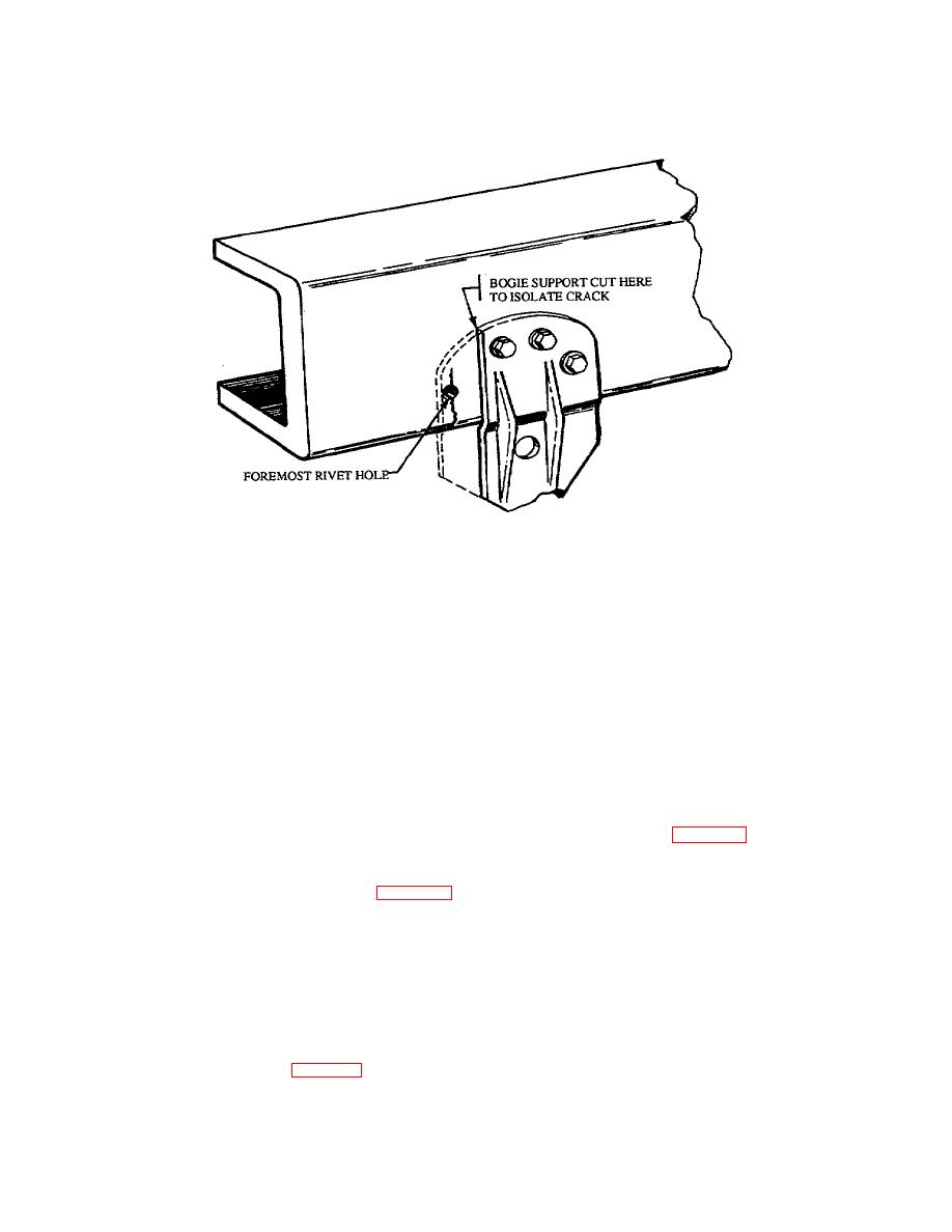
Figure 40. Isolation of Crack In Bogie Support
e. Thoroughly clean repaired
surfaces
and
55.
Defect. Cracks Under Bogie Support. Cracks
surrounding area of repair.
located under bogie supports requiring removal of the
support assembly.
f.
Prime and paint repair area and surrounding
surfaces as specified in TM-43-0139.
WARNING
56.
Defect. Cracks In Lower Flange of Frame
Use Only effective chip guarding
Rail. Cracks in lower flange of frame rail at the bogie
equipment, protective equipment and
support.
protective clothing (goggles, shields,
gloves aprons, etc) when doing any
a. Sketches. Prepare sketches to design specific
drilling, grinding, or welding. Failure
repair requirements as required and/or as shown
to follow this warning could result in
in this section.
injury to personnel.
b. Fabricate doubler plate from prepared sketches
a. Cut bogie support to provide space around the
and as shown in Figure 42.
area of the vehicle frame to be welded.
c.
Using C- clamps, insure that frame rails are in
b. Cut the support by drilling a series of holes at the
alinement and in close contact with the doubler.
proposed welding point as shown in figure 41.
Chisel through holes, and grind separated
d. Grove the side rail and weld into the liner with
surfaces to a smooth finish with a portable
the doubler plate in place.
grinding tool.
e. Thoroughly clean repaired
surfaces
and
c.
Sketches. Prepare sketches to design specific
surrounding area of repair.
repair requirements as required and/or as shown
in this section.
f.
Prime and paint repair area and surrounding
surfaces as specified in TM-3-01 39.
d. Fabricate and install doubler plate from prepared
sketches and as shown in figure 42.
36
|
|
Privacy Statement - Press Release - Copyright Information. - Contact Us |