 |
|||
|
|
|||
|
Page Title:
Defect. Cracks and Elongated Or Gouged Mounting Holes |
|
||
| ||||||||||
|
|
 TB 9-2300-247-40
b. Bevel edges of crack and weld to obtain
d. Weld additional plates on each end of
complete penetration.
crossmember as described in paragraph 6.
Plates shall be welded in area of highest density;
approximately 6 inches measured in from each
WARNING
end.
Use only effective chip guarding
e. Stress relieve all welded areas for one hour by
equipment, protective equipment and
heat treating at 11250 F., plus or minus 25 F.
protective clothing (goggles, shields,
gloves aprons, etc) when doing any
f.
Thoroughly clean repaired
surfaces
and
drilling, grinding, or welding. Failure
surrounding area of repair.
to follow this warning could result in
injury to personnel.
g. Prime and paint repair area and surrounding
surfaces as specified in TM-43-0139.
c.
Grind away excess metal of weld bead to
eliminate bead acting as stress raiser.
Figure 39. (Added) Repair of Cracked Frame Rails
c.
Bevel edges of V-shaped groove.
54.
Defect. Cracks and Elongated Or Gouged
CAUTION
elongated or gouged mounting holes detected forward of
No. 1 crossmember or to rear of bogie.
No weaving motion will be used
WARNING
during the welding process. Heat
and number of welding passes will be
Use Only effective chip guarding
kept to a minimum to prevent
equipment, protective equipment and
excessive heating of side rails
protective clothing (goggles, shields,
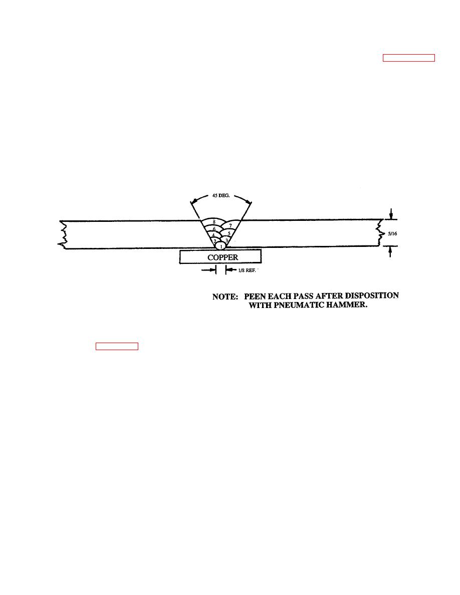
d. Obtain electrode type, MIL-308-MO-16, Class,
gloves aprons, etc when doing any
sized 1/8-inch or 3/32-inch, with maximum for
drilling, grinding, or welding. Failure
the welding process.
to follow this warning could result in
injury to personnel.
e. Using copper back-up, apply welded stringer
bead to each side of groove.
a. Drill a 2/16-inch diameter hole at the terminal
point of the crack.
f.
Apply channel flaseplating reinforcement plates
after welding as described in paragraph.
b. Grind a V-shaped groove along the edges of the
Thickness of flaseplating reinforcement shall be
crack, through the thickness of the cracked
equal to side rail thickness within 5/16-inch.
section.
Bolting instructions shall be as described in
paragraph.
35
|
|
Privacy Statement - Press Release - Copyright Information. - Contact Us |
