 |
|||
|
|
|||
|
Page Title:
Making an RF Transmitter Output Tester. |
|
||
| ||||||||||
|
|
 TM 5-4120-394-BD
SECTION III (Cont)
Field Expedient Test Equipment (Cont):
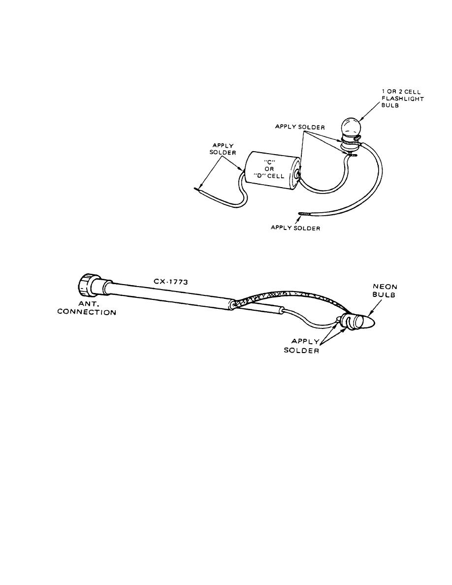
2. Making an Ohmmeter (continuity tester)
An ohmmeter can be made from a
flashlight bulb, flashlight battery, and
three pieces of wire. When the free
ends of the wires are touched to a
circuit where continuity (or a short)
exists, the bulb will glow. If a two-cell
flashlight bulb is used with only one
battery, the bulb will glow with one-half
its normal brilliance.
3. Making an RF Transmitter Output Tester.
This device is used to determine if the
radio is sending a signal to the
a.
An RF transmitter output tester can be made from a neon light bulb and a piece of CG-1773 RF cable.
Solder the bulb to the cable as shown in the illustration. Connect the cable to the ANT connection on the front of the radio.
When the radio is keyed, the bulb will glow if RF power is present at the antenna connection (this does not verify
transmitter frequency accuracy).
b.
Another way to check for transmitter output is to hold a common (wood) lead pencil tip 1/4-inch to 1/8-inch
from the ANT connection. If RF power is present, a yellowish-white arc will jump from the connector to the pencil tip when
the radio is keyed.
B-4
|
|
Privacy Statement - Press Release - Copyright Information. - Contact Us |