 |
|||
|
|
|||
|
|
|||
| ||||||||||
|
|
 FUEL SYSTEM
TESTING AND ADJUSTMENT
9. Adjust dial indicator (8) so both pointers (10) are on "0"
(Zero).
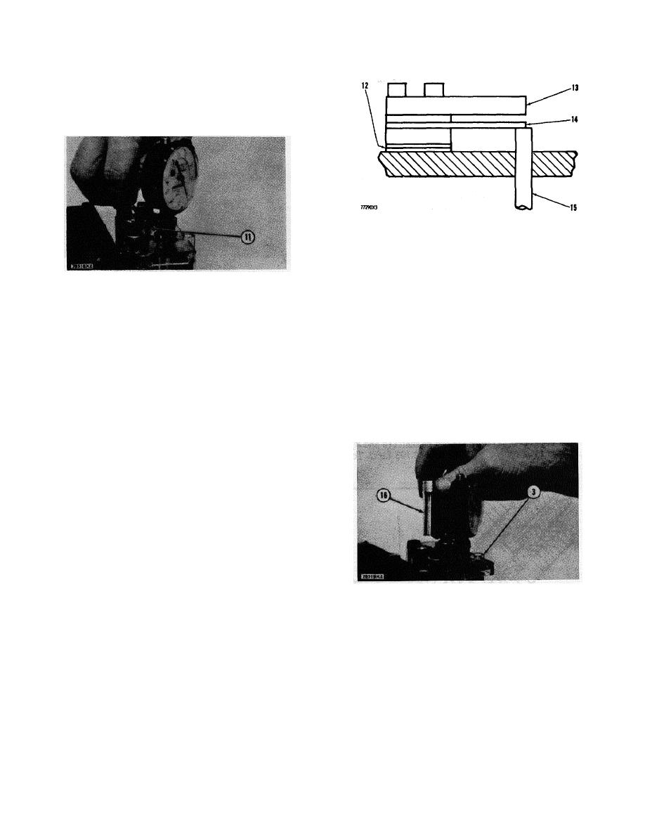
10. Using wrench (11) turn the 8S7271 Screw (6)
counterclockwise. Turn screw (6) six or more turns.
LEAF TYPE TORQUE SPRING
12. Location of shims. 13. Stop bar. 14. Leaf
type torque spring. 15. Load stop pin.
e. Install the correct amount of shims (12) torque
spring (14), and stop bar (13) on the housing for the
LOOSENING SCREW (6)
fuel injection pumps.
11. 1S9836 Wrench.
f. Install the test tools and do the test procedure again.
11. Put the clip end of the 8S4627 Circuit Tester to a good
Do this until the dimension on the dial indicator is
ground. Put the other end of the 8S4627 Circuit Tester
the same as the dimension given in the RACK
on the load stop contact. Put this end of the 8S4627
SETTING INFORMATION. After the fuel setting is
Circuit Tester through the large hole on top of cover
correct, remove the test tools. Install cover (2) and
(3).
shut-off solenoid (1).
12. Move the governor control lever to the LOW IDLE
Load Stop Adjustment
position.
a. Put socket (16) in the large hole in cover (3).
13. Move the governor control lever slowly toward the
HIGH IDLE position until the continuity light just comes
on. Make a note of the reading on dial indicator (8).
Do this step several times to make sure the reading is
correct.
14. Make a comparison of this reading and the fuel setting
in the RACK SETTING INFORMATION.
15. If the reading on dial indicator (8) is not correct, do the
following.
Leaf Type Torque Spring
PUTTING SOCKET IN COVER
a. Write down the dimension that is on dial indicator
3. 2P331 Cover. 16. 3P221 Socket.
(8).
b. Write down the dimension given in the RACK
b. Use wrench (21) with socket (16) and loosen locknut
SETTING INFORMATION.
(18).
c. Remove the test tools [cover (3), spring (4), and dial
c. Using screwdriver (20), turn adjustment screw (17)
indicator (10)] from the housing for fuel injection
until the reading on dial indicator (8) is the same as
pumps.
the dimension given in the RACK SETTING
d. Install or remove shims at location (12) to get the
INFORMATION.
correct dimension as given in the RACK SETTING
INFORMATION.
The difference between the
d. When the adjustment is correct, tighten locknut
dimensions in (a) and (b) is the thickness and
(18). Check the adjustment again by doing Steps
amount of shims to remove or install to get the
11 through 15 again.
correct setting.
59
|
|
Privacy Statement - Press Release - Copyright Information. - Contact Us |
