 |
|||
|
|
|||
|
Page Title:
OPERATION OF 9L7883 FUEL INJECTION NOZZLE |
|
||
| ||||||||||
|
|
 FUEL SYSTEM
SYSTEMS OPERATION
(90N1-90N6120)
The main components of a fuel injection pump
The compression seal goes against inlet fitting
in the sleeve metering fuel system are barrel (A),
(7) and prevents the leakage of compression from
plunger (B), and sleeve (D). Plunger (B) moves up
the cylinder. Carbon dam (13), at the lower end of
and down inside the barrel (A) and sleeve (D).
nozzle body (12), prevents the deposit of carbon in
Barrel (A) is stationary while sleeve (D) is moved
the bore in the cylinder head.
up and down on plunger (B) to make a change in
the amount, of fuel for injection.
Fuel, under high pressure from the fuel injection
pump goes through the hole in fuel inlet (7). The
When the engine is running, fuel under pressure
fuel then goes around valve (9), fills the inside of
from the fuel transfer pump goes in the center of
nozzle body (12) and pushes against valve guide
plunger (B) through fuel inlet (C) during the down
(6). When the force made by the pressure of the
stroke of plunger (B). Fuel can not go through fuel
fuel is more than the force of spring (4), valve (9)
outlet (E) at this time because it is stopped by
will lift. When valve (9) lifts, fuel under high
sleeve (D), (see position 1).
pressure will go through the four .0128 in. (0.325
mm) orifices (10) into the cylinder. When the fuel
Fuel injection starts (see position 2) when
is sent to the cylinder, the force made by the
plunger (B) is lifted up in barrel (A) enough to
pressure of the fuel in the nozzle body will become
close fuel inlet (C). There is an increase in fuel
less. The force of spring (4) will then be more than
pressure above plunger (B), when the plunger is
the force of the pressure of the fuel in the nozzle
lifted by camshaft (4). The fuel above plunger (B)
body. Valve (9) will move to the closed position.
is injected in to the engine cylinder.
Injection will stop (see position 3) when fuel
Valve (9) is a close fit with the inside of nozzle
outlet (E) is lifted above the top edge of sleeve (D)
tip (14), this makes a positive seal for the valve.
by camshaft (4). This movement lets the fuel that
is above, and in, plunger (B) go through fuel outlet
When the fuel is sent to the cylinder, a small
(E) and return to the fuel injection pump housing.
quantity of fuel will leak by valve guide (6). This
fuel gives lubrication to the moving parts of the
When the sleeve (D) is raised on plunger (B), fuel
fuel injection nozzle This fuel then goes through a
outlet (E) is covered for a longer time, causing
leak off boot at the top of nozzle body (12) and is
more fuel to be injected in the engine cylinders. If
returned to the fuel tank.
sleeve (D) is low on plunger (B), fuel outlet (E) is
covered for a shorter time, causing less fuel to be
FUNCTION OF FUEL JUNCTION BLOCK
injected.
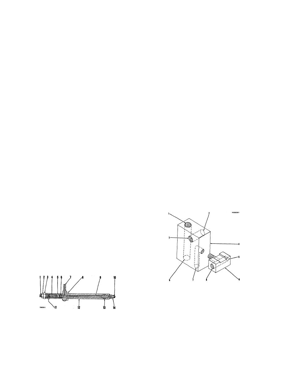
OPERATION OF 9L7883 FUEL INJECTION NOZZLE
The fuel inlet (7) and nozzle tip (14) are parts of
the nozzle body (12). Valve (9) is held in position
by force of spring (4). Force of spring (4) is
controlled by shims (11). The lift of valve (9) is
controlled by lift adjusting screw (1). Locknut (2)
holds lift adjusting screw (1) in position. Compres-
sion seal (8) goes on nozzle body (12).
CONNECTIONS FOR FUEL LINES AT
THE FUEL JUNCTION BLOCK
1. Connection for constant bleed line to fuel tank. 2.
Connection for fuel supply line to fuel tank. 3. Connection
for fuel supply line to fuel filter. 4. Fuel injunction block. 5.
Connection for bleed line for fuel injection nozzles to fuel
FUEL INJECTION NOZZLE
tank. 6. Connection for constant bleed line to housing for
1. Lift adjusting screw. 2. Locknut. 3. Pressure screw.
fuel injection pumps. 7. Connection for bleed line for fuel
4. Spring. 5. Spring seat. 6. Valve guide. 7. Fuel
injection nozzles on right side of engine. 8. Connection for
inlet. 8. Compression seal. 9. Valve. 10. Orifices
bleed line for fuel injection nozzles on left side of engine. 9.
four). 11. Shims. 12. Nozzle body. 13. Carbon dam.
Tee.
14. Nozzle trip.
7
|
|
Privacy Statement - Press Release - Copyright Information. - Contact Us |
