 |
|||
|
|
|||
|
Page Title:
FLOW OF FUEL USING THE PRIMING PUMP |
|
||
| ||||||||||
|
|
 FUEL SYSTEM
SYSTEMS OPERATION
(90N1-90N6120)
rpm and position of governor weights (28). Any
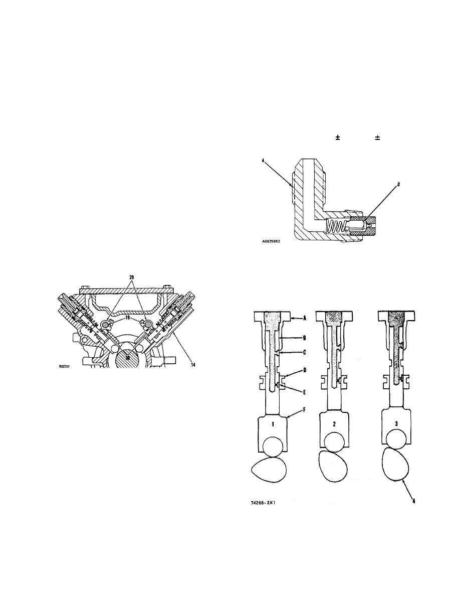
CONSTANT BLEED VALVE
change of governor weight position will cause
thrust collar (25) to move. As governor weights
Constant bleed valve (4) lets approximately 9
(28) turn faster, thrust collar (25) is pushed toward
gallons of fuel per hour go back to fuel tank (7).
governor springs (23). When the force of governor
This fuel goes back to fuel tank (7) through return
springs (23) is balanced by the centrifugal force of
line for constant bleed valve (3). This flow of fuel
the governor weights, sleeves (30) of the injection
removes air from housing (14) and also helps to
pumps are held at a specific position to send a
cool the fuel injection pump. Check valve (D)
specific amount of fuel to the engine cylinders.
makes a restriction in this flow of fuel until the
pressure in housing (14) is at 8 3 psi (0.6 0.2
When the governor control lever is turned
kg/cm2 ).
toward the FUEL-OFF position with the engine
running, there is a reduction of force on governor
springs (23). The movement of the linkage in the
governor will cause fuel control shafts (19) to
move sleeves (30) down, and less fuel will be
injected in the engine cylinders.
To stop the engine, turn the ignition switch to
the "OFF" position. This will cause the shut-off
solenoid to move linkage in the fuel pump housing.
Movement of the linkage will cause sleeve levers
(29) to move sleeves (30) down, and no fuel is sent
to the engine cylinders. With no fuel going to the
CONSTANT BLEED VALVE
engine cylinders, the engine will stop.
4. Constant bleed valve. D. Check valve.
OPERATION OF FUEL INJECTION PUMPS
FUEL SYSTEM COMPONENTS
14. Housing for fuel injection pumps. 19. Sleeve control
shafts. 29. Sleeve levers. 30. Sleeves.
FLOW OF FUEL USING THE PRIMING PUMP
When the handle of priming pump (2) is pulled
out, negative air pressure in priming pump (2)
opens check valve (A) and pulls fuel from fuel tank
(7). Pushing the handle in closes check valve (A)
and opens check valve (B). This pushes air and/pr
fuel into housing (14) through the fuel passages
and check valve (C). More operation of priming
pump (2) will pull fuel from fuel tank (7) until the
fuel lines, fuel filter (9) and housing (14) are full of
fuel. Do this until the flow of fuel from manual
FUEL INJECT!ON SEQUENCE
bleed valve (5) is free of air bubbles. Relief valve
1, 2. 3. Injection stroke (positions) of a fuel injection pump.
(10) will open and let the fuel go to the inlet for
4. Injection pump camshaft. A. Barrel. B. Plunger. C.
fuel priming pump (2} if the pressure gets higher
Fuel inlet. D. Sleeve. E. Fuel outlet. F. Lifter.
than 20 psi (1.4 kg/cm ) when using priming pump (2).
6
|
|
Privacy Statement - Press Release - Copyright Information. - Contact Us |
