 |
|||
|
|
|||
|
|
|||
| ||||||||||
|
|
 TM 5-3815-223-14&P
4. The fairlead can be locked into position using pin (09)
3. Rotate the drum to remove one-half of the lagging at
and hair pin (10). Rotate the fairlead so the sheaves are
a time.
up and down, then insert pin (09) into fairlead head block
4. Remove the cotter pins, lockwashers, and nuts
( 1 ) and into plate (12). Install hair pin (10).
securing the drum laggings together.
5. Remove the tie wire, capscrews and lockwashers
NOTE
securing the top half of lagging.
To fully lower the boom remove pin
6. Rotate the drum and remove the tie wire, capscrews
(03) closest to centerline of revolving
and lockwashers securing the other half of the lagging.
frame and swing the fairlead out of
7. Set the new half piece of lagging on the drum.
the way.
Secure with the lockwashers, capscrews and tie wire.
Rotate the drum and repeat the procedure with the other
REEVING. Reeving and rope size information for the
half of lagging.
drag- line (and a clamshell if used) are shown in Figure
8. Install the rod bolt, lockwashers, nuts and cotter pins
to secure the two drum laggings together.
9. Install the sheet metal removed to gain access to the
REMOVING FAIRLEAD
lagging mounting hardware.
To remove the fairlead proceed as follows (see Figure
10. Reinstall the wire rope.
1. Remove hair pin (10) and pin (09) to unlock fairlead.
FAIRLEAD SERVICE
2. Remove locknut (08), lockwasher (07) and bearing
GENERAL. Fairlead service is limited to replacement of
retainer (06). Remove sheave assembly (05).
bearings in the sheave assembly and replacement of the
3. See Figure 3 and disconnect cord grip at limit switch.
rollers.
Remove electrical lead from fairlead bracket. Coil up
FAIRLEAD SHAFT BEARING REPLACEMENT. To
electrical lead and store for future use.
replace the bearings in the fairlead shaft proceed as
4. Support fairlead bracket (01) and remove hair pins
follows (see Figure 7):
(04) and pins (03). Remove bracket (01).
1. Unlock fairlead by removing hair pin (01) and pin (02).
2. Remove locknut (03), lockwasher (04) and bearing
DRAGLINE BOOM POINT
retainer (05). Remove sheave assembly (06).
The boom point used on the dragline is a single sheave
3. Remove bearing (07), spacer (08) and bearing (09)
with a dirt guard. See Figure 5 for the dragline boom
from fairlead shaft. Remove bearing retainer (10).
point.
Inspect bearings and replace if necessary.
4. Install bearing retainer (10), bearing (09), spacer (08)
LAGGING
and bearing (07).
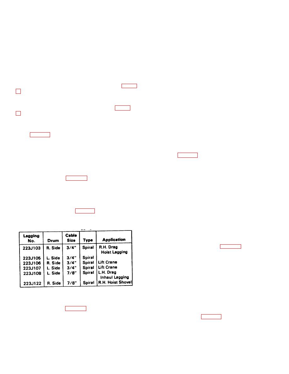
GENERAL.
Different types of lagging are used
5. Set sheave assembly (06) into fairlead head and
depending upon the cable size and application (liftcrane,
secure with bearing retainer (05), lockwasher (04) and
clamshell, dragline, etc.). Table 1 lists the laggings
nut (03).
used on this machine.
6. Lubricate bearing cavity with GAA grease.
7. Rotate sheave assembly (06) into position. Install pin
Table 1. Laggings
(02) and hair pin (01).
FAIRLEAD SHEAVE REPLACMENT. To replace the
sheave, proceed as follows (see Figure 8):
1. Remove capscrew (01) and lockwasher (02).
2. Remove rod end (03) and remove pin (04). Remove
sheave (05) from sheave assembly (06).
3. Inspect the bearings in the sheave and replace if
necessary.
4. Install sheave (05) into sheave assembly(06) and
secure with pin (04).
5. Install rod end (03) into pin (04) and secure with lock-
washer (02) and capscrew (01).
CHANGING LAGGING. To change lagging does not
6. Lubricate sheave bearings with GAA grease.
require drumshaft removal. To change the lagging,
proceed as follows (see Figure 6):
ROLLER ASSEMBLY. To repair the roller assembly,
proceed as follows (see Figure 9 ):
1. Remove all wire rope from the drum.
2. Remove the sheet metal from around both ends of
the drum to gain access to the capscrews and
lockwashers securing the lagging to the drum.
2
|
|
Privacy Statement - Press Release - Copyright Information. - Contact Us |
