 |
|||
|
|
|||
|
Page Title:
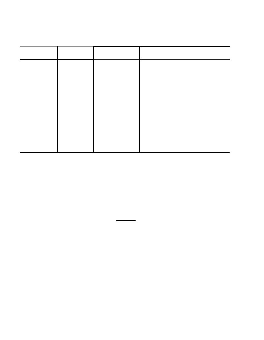
Table 5-9. Indicator Lamp Assembly (A18, A19), Inspection |
|
||
| ||||||||||
|
|
 TM 32-5865-069-24&P
Indicator Lamp Assembly (A18, A19), Inspection
Inspection
Normal
Procedure
Component
method
condition
Indicator
Visual
a thru d must
a.
Check the assembly for
loose, missing or damaged
be free of
Light Assy
defects.
hardware.
b.
Check lamp contacts for
dirt, corrosion and damage.
Check for continuity between
c.
lamp contacts and printed
wiring board connections
using a multimeter.
Examine the printed wiring
d.
board, check-for broken or
cracked board, dry joints or
excessive solder, lifted or
broken tracks.
(3) Insert the blade of the screwdriver between the retaining spring and
the top of the sleeve. Gently depress the spring to release the
.
assembly from the sleeve.
(4) Ensure the replacement lens is fitted with serviceable lamps.
(5) Insert the lens into the sleeve and push gently until the retaining
spring snaps into place.
b. Replace Indicator Assembly/Printed Wiring Board as follows:
CAUTION
Use a low temperature soldering iron tip or appropriate heat-sink to
avoid damage to printed wiring board.
Refer to NAVTORPSTA REPORT
1347
(1) Use solder wick or suction to remove solder from all connections to
the printed wiring board.
(2) Remove and retain the four screws securing the printed wiring board to
the assembly.
(3) Remove the board from the assembly.
(4) Discard the faulty component.
(5) Assemble the replacement part to the component retained in step b.(4).
5-46
.
|
|
Privacy Statement - Press Release - Copyright Information. - Contact Us |
