 |
|||
|
|
|||
|
|
|||
| ||||||||||
|
|
 TM 3-4240-284-30&P
2-15. COMPARTMENT CONTROL MODULE - MAINTENANCE INSTRUCTIONS (Cont).
LOCATION
ITEM
ACTION
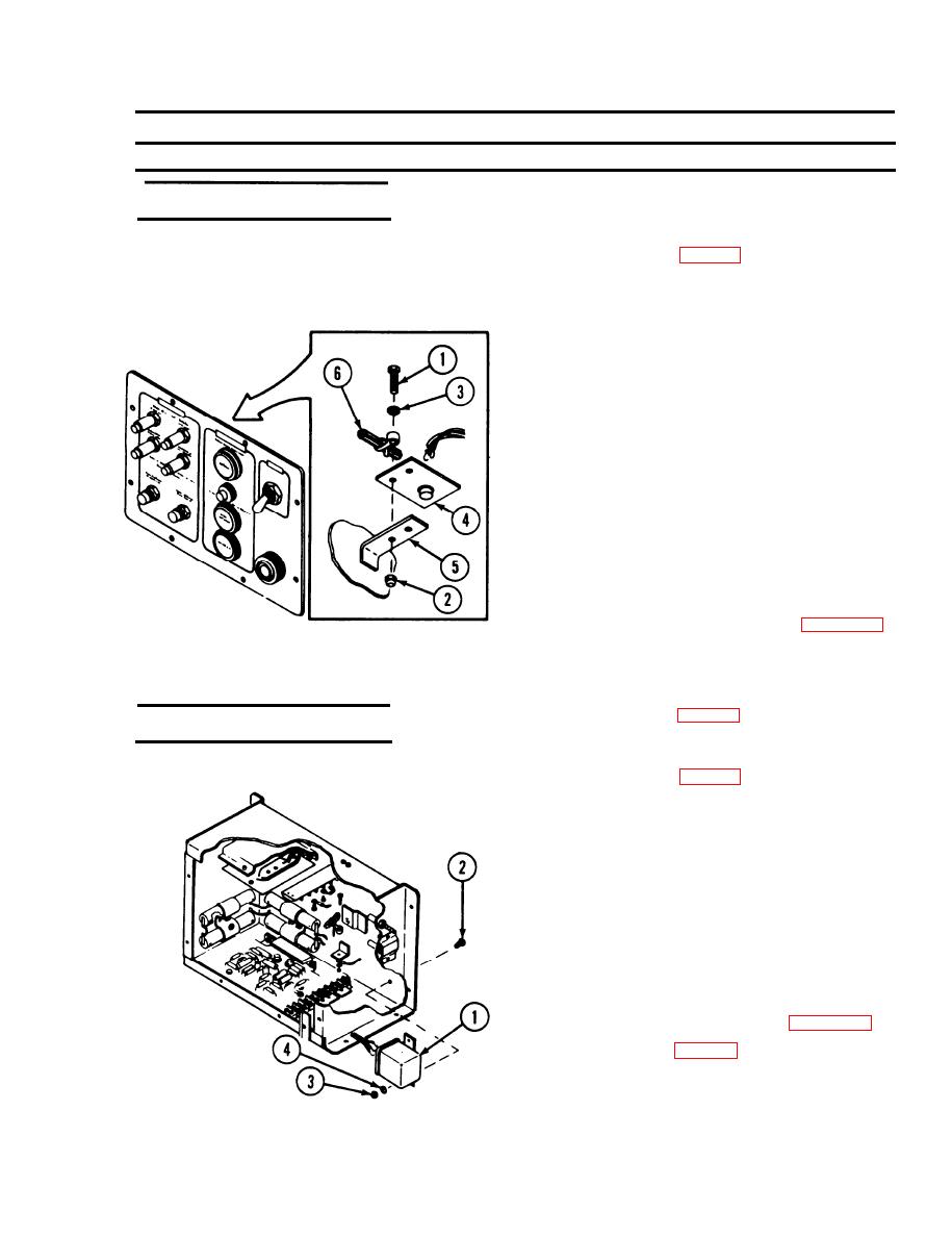
REMOVAL/lNSTALLATION
REMOVAL
Panel
Printed circuit assembly
1. Disassemble CCM (p 2-171),
(auxiliary switching)
2. Remove two screws (1), nuts (2), and washers (3)
3. Unsolder wires and remove auxiliary switching
printed circuit assembly (4).
CAUTION
Apply needle-nose pliers to the leads of the
diodes connected between terminals 1 and
2, 3 and 8, and 7 and 8 to form a heat sink
during soldering of these terminals. This is
done to prevent heat damage to the diodes.
Use care to apply only enough heat as
necessary to form a good solder joint. This
applies to all terminals.
INSTALLATION
1., Connect and solder wires to auxiliary switching
printed circuit assembly (4). Refer to page 2-184.
2. Place auxiliary switching printed circuit assembly (4)
on bracket (5) and attach using screws (1),
washers (3), cable bracket (6), and nuts (2).
3. Reassemble CCM (p 2-171).
REMOVAL/INSTALLATION
REMOVAL
Housing
Flasher
1. Disassemble CCM (p 2-171).
2. Unsolder wires from flasher (1).
3. Remove two screws (2), nuts (3), and washers (4).
4. Remove flasher (1).
INSTALLATION
1. Install flasher(1) using two screws (2), washers (4),
and nuts (3).
2. Connect and solder wires. Refer to page 2-184.
3. Reassemble CCM (p 2-171).
2-175
--
|
|
Privacy Statement - Press Release - Copyright Information. - Contact Us |
