 |
|||
|
|
|||
|
|
|||
| ||||||||||
|
|
 TM 3-4240-284-30&P
ITEM
ACTION
LOCATION
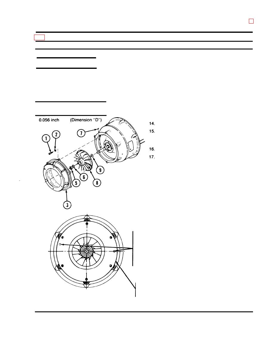
REASSEMBLY (Cont)
Main Fan
12. Subtract dimension "B" from dimension "A" as re-
corded in steps 10 and 11, the difference being
Example
dimension "C". (See example below.)
(Dimension "A")
1.152 inches
13. Subtract a nominal 0.010 inch from dimension "C"
(Dimension "B")
1.086 inches
and record as dimension "D" Dimension "D" is the
required shim thickness for shim to obtain 0.007 to
(Dimension "C")
0.066 inch
0.012 inch axial clearance between the fan impeller
(Nominal)
-0.010 inch
and the impeller cover.
Remove impeller cover and impeller.
Peel laminated shims (9) to required thickness de-
termined by dimension "D" to obtain the proper
spacing.
Install shims (9) on rotor shaft.
Install woodruff key (7) in rotor shaft and install fan
impeller (8).
18. Install washer (6) and lock nut (5).
19. Torque lock nut (5) to 95 to 110 inch-pounds.
20. Turn rotor counterclockwise to check that bearings
are free.
21. With the stator electric cable positioned in the 6
o'c!eck position, install the impeller cover (3) with
the installation locating holes located in the 3
o'clock and 9:30 positions.
22. Install six washers (2) and screws (1).
LOCATION OF
INSTALLATION
HOLES (WITH
STATOR CABLE
ON OUTPUT END
AT 6 O'CLOCK
POSITION)
IMPELLER COVER
VIEWED FROM
INPUT END
2-149
|
|
Privacy Statement - Press Release - Copyright Information. - Contact Us |
