 |
|||
|
|
|||
|
|
|||
| ||||||||||
|
|
 TM 3-4240-284-30&P
2-11. MAIN FAN - MAINTENANCE INSTRUCTIONS (Cont).
ITEM
ACTION
LOCATION
REASSEMBLY (Cont)
.
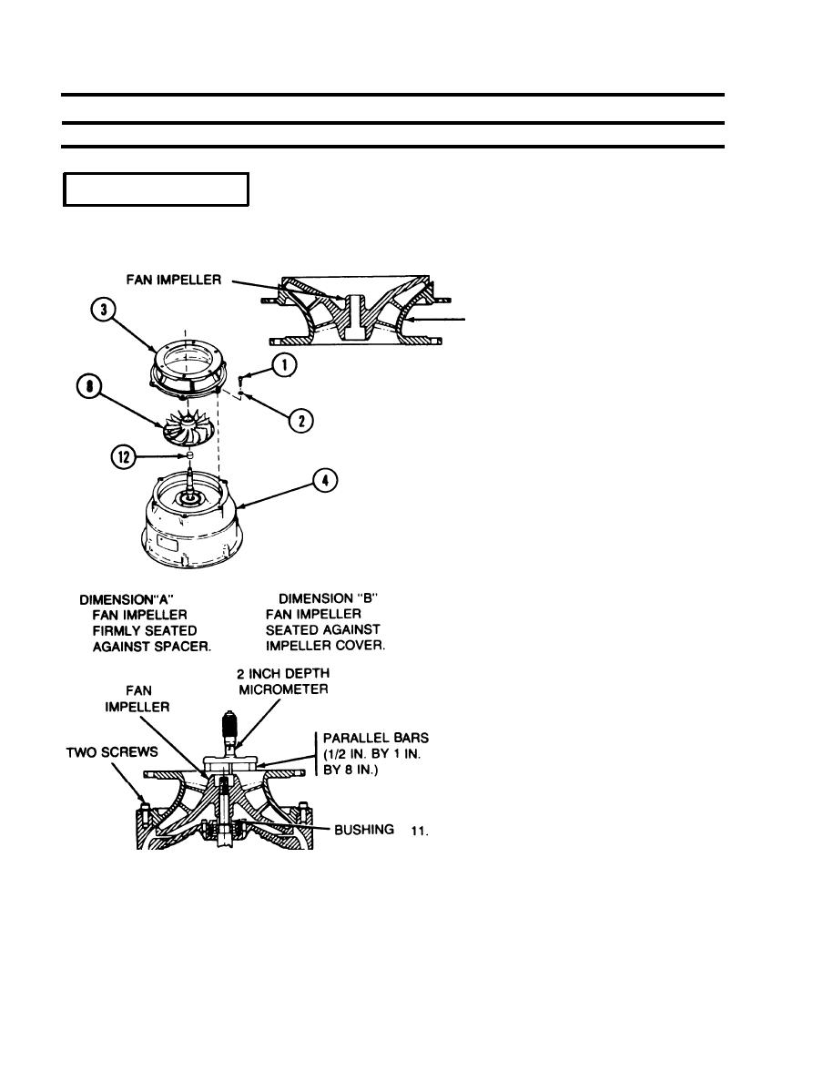
5. Check the contour fit between the fan impeller and
Main fan
the impeller cover.
IMPELLER COVER
6. Position the fan housing (4) vertically with input end
up.
7. Install bushing (12) on rotor shaft.
8. Install the fan impeller (8) on the rotor shaft without
the woodruff key. Do not install self locking nut.
9. Install the impeller cover (3) on the fan housing and
secure with two screws (1) and two washers (2) 180
degrees apart.
NOTE
The fan impeller must be firmly seated
against the bushing on the rotor shaft in
order to obtain an accurate reading for
dimension "A".
10. With the fan impeller against bushing, use a 2 inch
depth micrometer with two parallel bars (1/2 inch by
1 inch by 8 inches). Measure the distance from the
top of the parallel bars to the machined surface on
the fan impeller as shown. Record as dimension
"A".
NOTE
The fan impeller must be firmly seated
against the impeller cover to obtain an accu-
rate reading for dimension "B".
Pull up on the fan impeller to seat against the
impeller cover and take a second measurement
using the same technique as in step 10 and record
IMPELLER GAGE DIAMETER. (ADD SHIMS
as dimension "B".
BETWEEN IMPELLER AND SPACER TO
OBTAIN 0.007 TO 0.012 INCH AXIAL
CLEARANCE BETWEEN FAN IMPELLER
AND IMPELLER COVER.)
2-148
|
|
Privacy Statement - Press Release - Copyright Information. - Contact Us |
