 |
|||
|
|
|||
|
Page Title:
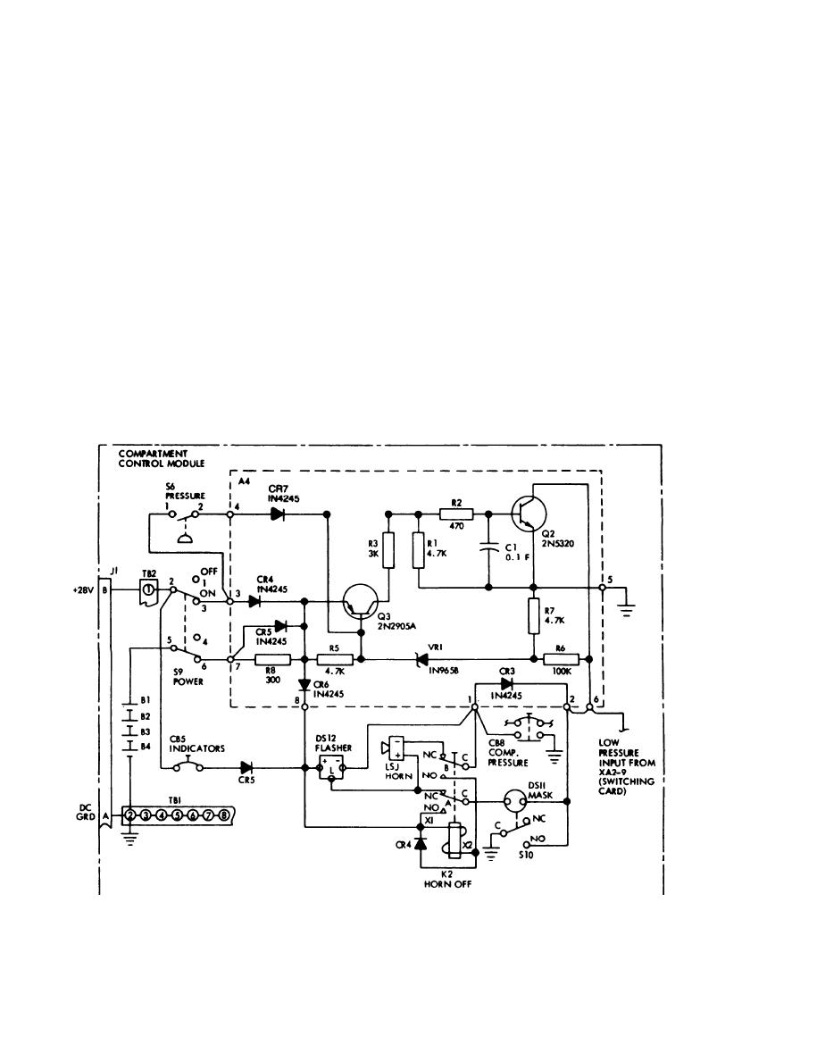
LOSS OF POWER/PRESSURE WARNING SYSTEM |
|
||
| ||||||||||
|
|
 TM 3-4240-284-30&P
power feedback into the rest of the 28 vdc power sys-
1-11. LOSS OF POWER/PRESSURE WARNING
tem. Diode CR3 provides power for the MASK indicator
SYSTEM.
press-to-test. Diode A4 CR6 blocks power to the loss of
a. The loss of power warning system provides an
power warning system when the system is off; however,
alarm, mask light and warning horn whenever the power
press-to-test power is being provided through CR5.
switch on the compartment control module is turned on
c. During normal operation, 28 vdc power is provided
in the absence of input power to the compartment con-
through the closed contacts of pressure switch S6 and
trol module. An alarm is also provided when power is
diode A4 CR7 to keep A4 Q3 turned off. Whenever there
lost during normal operation.
is a loss of pressure or a loss of power, 28 vdc is
b. When the compartment control module power
removed from the base of A4 Q3 and battery current
switch is ON and the power is provided to the modular
provided by A4 R5, A4 VR1, and A4 R7 turns A4 Q3 on.
collective protection equipment, the batteries are
Current provided by A4 Q3 and A4 R3 is directed to the
charged through normal power distribution in the com-
base of A4 Q2 turning A4 Q2 on. When A4 Q2 is on, a
partment control module through charging resistor R8.
ground is provided at terminals 1,2, and 6 of A4 which
With the compartment control module power switch ON
activates the warning circuit.
and a loss of power, battery power is provided to the loss
d. Current will be supplied by A4 Q3 as long as the
of power warning system through terminals 5 and 6 of
battery voltage is greater than 16 volts. In the range of
the compartment control module power switch of termi-
14-16 volts the transistor A4 Q3 will be turned off by A4
nals 7 of A4 (printed circuit assembly switching
VR1 thus removing base drive for A4 Q2 and hence
auxiliary). Power is provided to the warning devices
turning off the warning circuit and preventing deep dis-
from terminal 8 of A4. Diodes A4 CR4 and CR5 prevent
charge of the batteries.
Loss of Power/Pressure Warning System Schematic Diagram
1-4
|
|
Privacy Statement - Press Release - Copyright Information. - Contact Us |
