 |
|||
|
|
|||
|
Page Title:
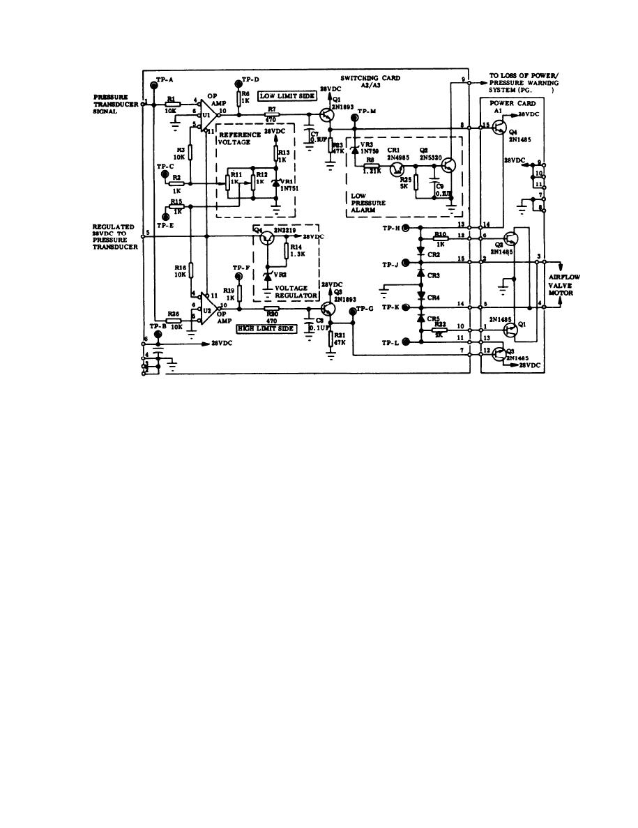
Pressure Control System, Switching and Power Card, Interconnection Schematic |
|
||
| ||||||||||
|
|
 TM 3-4240-284-30&P
Pressure Control System, Switching and Power Card, Interconnection Schematic
motor. The voltage increases at the rate of 5.1 volts/.1
c. Direct current power and ground are provided at
in. wg and saturates or reaches a maximum of about 25
output terminals 3 and 4 of the power card to the
volts when the pressure is 0.35 in. wg or more outside of
reversible 28 vdc motor. As the output of Q4 on the
the dead band.
power card starts to rise, it provides current via RI O to
e. The switching card also contains the low pres-
the base of Q2 on the power card. When this happens,
sure alarm circuitry consisting basically of Q2, CR1,
Q2 turns on and provides a ground at terminal 4 of the
VR3, and the voltage divider resistors R8 and R25. This
power card whenever a voltage greater than a few volts
circuit is set to fire when the pressure falls below a
is provided at terminal 3 of the power card. The airflow
preset level, 1.0 in. wg for the compartment control
valve motor is connected such that when this happens
module and 0.33 in. wg for the protective entrance con-
the airflow valve motor will start and open the valve until
trol module. When the pressure reaches the levels
the compartment pressure has risen to within the pre-
described above, the voltage across the four layer diode
scribed limits.
d. The description so far has been only for a low
goes down to about 1 volt and allows base current to
flow into the transistor Q2. The transistor is, therefore,
pressure condition or low limit side. There is an equiva-
"on" and provides aground at terminal 9 of the switching
lent high pressure or high limit side circuitry which pro-
vides opposite polarity voltage to terminals 3 and 4 of
card. In the system when this ground is provided, the
MASK light/hem alarm or PE LOW PRESSURE light
the power card and hence the airflow valve motor. This
comes on. The circuit turns off when the voltage level of
circuitry consists of U2, Q3 on the switching card, and
Q3 and Q1 on the power card. Whenever one pressure
the low limit side falls within the proper limits.
f. The circuit consisting of R14, VR2, and Q4 is a
side is on, the other side is off. In the dead band (i.e.,
when the pressure is within the proper limits), both sides
series voltage regulator for the op amps and the pres-
are off. The greater the pressure is outside the dead
sure transducer. The circuit limits the voltage of these
band, the greater the dc voltage to the airflow valve
components to 28 vdc during high voltage transients.
1-3
|
|
Privacy Statement - Press Release - Copyright Information. - Contact Us |
