 |
|||
|
|
|||
|
|
|||
| ||||||||||
|
|
 TM 3-4240-284-20&P
ITEM
ACTION
LOCATION
TEST
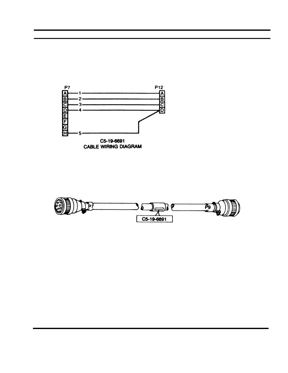
Power Distribution Unit
Check continuity of each wire between P7 and P12.
cable C5-19-6691
and Power Source
Connector
NOTE
Use multimeter and cable
C5-19-6691 wiring diagram.
REPLACE
Power Distribution Unit
cable C5-19-6691
Replace cable if it fails continuity check.
and Power Source
Connector
INSTALLATION
WARNING
High voltage is used to power this equipment. Before installing power cable, be sure that POWER
switch on compartment control module is in the OFF position and that the collective protection
equipment power source is shut down to avoid personal injury or loss of life.
Power Distribution unit and cable C5-19-6691
Set compartment control module POWER switch (1) to
OFF.
Power source connector
Connect cable assembly plug P9 (4) to power source
connect J9 (5) at feed thru.
connect cable assembly plug P7 (2) to power
distribution unit connector J7 (3).
2-107
|
|
Privacy Statement - Press Release - Copyright Information. - Contact Us |
