 |
|||
|
|
|||
|
|
|||
| ||||||||||
|
|
 TM 3-1040-220-34&P
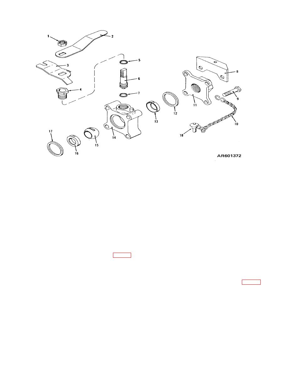
1 Nut
10 Chain and Slink
2 Handle
11. Flange
3 Lock stop plate
12 Body seal
4 Locknut
13 Seat ring
5 Thrust washer
14 Valve body
6 Valve stem
15 Ball
7 Stem seal
16 Seat ring
8 Lock plate
17 Body seal
9 Bolt
18 Quick-release pin
Figure 2-4. Ball valve.
2-8. Ball Valve
a. Description and Function. The ball valve fig. 2-4 is
(1) Disassembly. The ball valve should be disassembled
a lever-actuated valve used to control the flow of agent
and cleaned after every mission. To disassemble the
under pressure from the agent tank. The valve is closed
ball valve, proceed as follows:
(a) Perform
when the handle (2) is turned perpendicular to the hose.
decontamination operations described in TM 3-1040-
Turning the handle parallel to the hose opens it. The
220-12&P.
handle is secured in the closed position by the quick
(b) Remove quick release pin (18, fig. 2-4) and
release pin (18), which must be removed before the
chain and S link (10) from flange (11) and valve body
handle can be operated.
(14) by removing bolt (9).
b.
Maintenance.
Direct support
maintenance
(c) Remove nut (1) from valve stem (6).
personnel are authorized to repair the ball valve by
(d) Remove handle (2).
replacing the components which are supplied as a repair
(e) Lift off lock stop plate (3).
kit.
(f) Remove locknut (4).
(g) Pull up and remove valve stem (6).
2-10
|
|
Privacy Statement - Press Release - Copyright Information. - Contact Us |
