 |
|||
|
|
|||
|
Page Title:
Indicator, Channel Alignment lD-1189/PR, Stopping Procedure |
|
||
| ||||||||||
|
|
 TM 11-6625-937-12
NOTE
Be sure a good BA-399/U is used in XMTR BAT. receptacle.
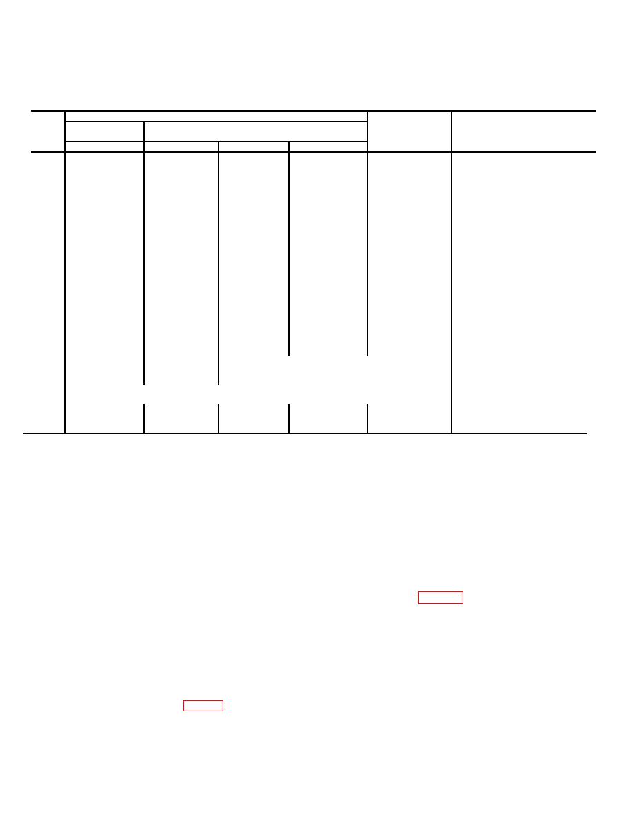
Control settings
Adjustment
Step
ID-1189/PR
AN/PRT-4
figs. 3-9 and 3-10
Adjust for
No.
FUNCTION
TEST PROBE
TONE-VOICE
CH-1, CH/2
1
VFO
TP 1
VOICE
CH-1
C27
Midscale meter indication. Slight
back and forth adjustment of C27
should cause meter pointer to
deflect back and forth between
calibration marks each side of
center mark.
2
VFO
TP 1
VOICE
CH-2
R36
Midscale meter indication. Slight
back and forth adjustment of R36
should cause meter pointer to
deflect back and forth between
calibration marks each side of
center mark.
3
RF
Remove
VOICE
CH-1
C43
Maximum meter indication. Turn
from
C43 clock wise to reduce reading
TP 1
to % of its maxi mum indication
4
RF
----------
VOICE
CH-1
C45
Maximum meter indication.
5
RF
----------
VOICE
CH-1
C51
Minimum meter indication.
6
RF
---------
VOICE
CH-5
C43
Maximum meter indication.
Repeat steps 1 and 2, and then proceed to step 8
7
Reassemble AN/PRT-4. Plug alignment indicator antenna into XMTR ANT jack. Place AN/PRT-4 1 to
8
2 feet from alignment indicator antenna with AN/PRT-4 antenna fully extended.
9
XMTRANTJ
--------
VOICE
CH-1
Loading
Maximum meter indication.
coil.
39. Indicator, Channel Alignment
lD-1189/PR, Stopping Procedure
a. Turn the FUNCTION switch to OFF.
b. Replace the instruction plates under their respective clips in the ID-1189/PR case cover.
c. Replace the screwdriver and alignment tool in their respective clips in the cover.
d. Replace the ID-1189/PR antenna in the case cover. The top of the antenna fits under the top clip. Coil the antenna
around the side of the cover and place the bottom of the an- tenna under the bottom retaining clip.
e. If the ID-1189/PR will not be used for 1 day or more, remove the battery (para 3-3c). For ID-1189(XE-2)/PR, the
battery must be removed to close the case.
f. Place the TEST PROBE in its retaining rubber grommet.
g. Place the RECVR OUTPUT plug in its retaining jack. For the ID-1189(XE-2)/PR, the battery adapter and the
RECEIVER ALIGNMENT adapter may be left installed or placed in their respective positions in the case lid (fig. 3-1.1).
h. Swing the case cover down and center it over the bottom portion of the case. Place the bottom of each front latch
under its respective latch strike (fig. 2-2).
i. Close the front latches by pushing up and against the lid. Close the rear latches in the same manner.
Change 2
3-16
|
|
Privacy Statement - Press Release - Copyright Information. - Contact Us |