 |
|||
|
|
|||
|
|
|||
| ||||||||||
|
|
 TM 11-6625-937-12
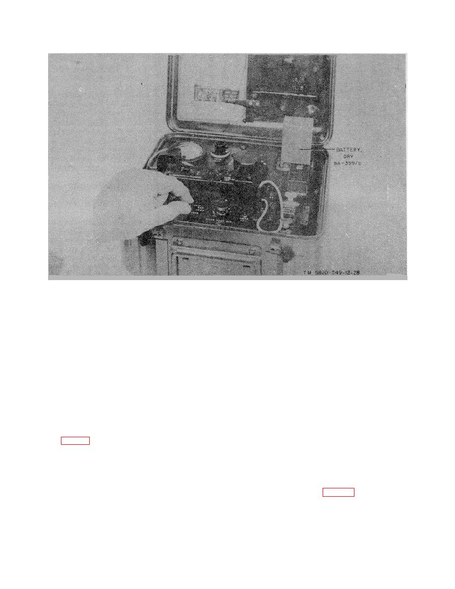
Figure 3-3. Indicator, channel alignment ID-1189/PR, AN/PRT-4 battery BA-399/U.
3-4. Preparation for Alignment
CAUTION
Never use the alignment tool to loosen retaining screws or an a common screwdriver;
this may damage the alignment tool blade.
a. Tools. All tools necessary for removal of parts and alignment adjustments are contained in the lid of the ID-
1189/PR (Figs. 1-1 and 1-1.1). The screwdriver with the wood handle is used to remove screws retaining the AN/PRR-9
electronic assembly (AN/PRR-9(XE-9), and the AN/PRT-4 cover plate (TM 11-5820-549-12 and TM 11-5820-549-12-1).
The alignment tool has a short metal blade and a long handle, and is used for turning all adjustment screws during
alignment. The alignment tool or screwdriver is removed from the holding clip by pressing the tops of the pair of prongs
toward the top of the individual prong with one hand while sliding the tool sideways out of its clipped position.
b. Preparing AN/PRR-9 for Alignment. Remove the AN/PRR-9 electronic assembly from its case (TM 11-5820-549-
12). Slide the AN/PRR-9 electronic assembly, component side up, into the ID-1189/PR RECEIVER ALIGNMENT
receptacle (fig. 3-4). Guide the battery pins of the AN/PRR-9 electronic assembly into the receptacle at the top left part
of the RECEIVER ALIGNMENT receptacle. The AN/PRR-9 adjustments and test points are then accessible through the
holes in the top plate of the RECEIVER ALIGNMENT receptacle. Tighten the receiver screw (fig. 3-1) under the
electronic assembly headset jack so that the electronic assembly is held firmly in the RECEIVER ALIGNMENT
receptacle.
c. Preparing ANIPRT-4 for Alignment. Remove the AN/PRT-4 antenna, battery, battery case, and cover plate (TM
11-5820-549-12). Insert a BA-399/U into the XMTR BAT. receptacle and test the battery (para 3-3b). A BA-399/U that
tests GOOD must remain in-
Change 5 34
|
|
Privacy Statement - Press Release - Copyright Information. - Contact Us |
