 |
|||
|
|
|||
|
Page Title:
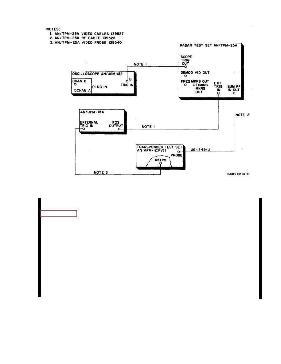
Figure 7.1-2 Depot overhaul standards basic test setup |
|
||
| ||||||||||
|
|
 TM 11-6625-667-45/NAVAIR 16-30APM123-2/T0 33A1-3-367-22
Figure 7.1-2 Depot overhaul standards basic test setup.
DELAY TIME
MULTIPLIER
09
a. Perform the initial setup procedures given in
f. On the test set, set CODE switches to 0000.
g. On the AN/USM-182, adjust DELAY
b. Connect AN/TPM-25A cable 139527 be-
TIME MULTIPLIER to position the center
tween AN/TPM-25A FREQ MKRS OUT and
(1090 MHz frequency marker on the center
AN/USM-182 CHANNEL B input.
graticule of the oscilloscope. Note that the 1
c. Connect AN/USM-182 CHANNEL A input
MHz markers appear on vertical lines two
to A8TP2 on the AN/APM-123.
divisions from the center. Each divison on the
d. On the AN/TPM-25A, make the following
oscilloscope represents .5 MHz.
control changes:
h. While observing the frequency markers on
REPLIES SIF REPLY CODE 0000
CHANNEL 3 and the reply video on CHANNEL
SWP 5
SIG GEN FUNCTION
A, adjust AN/TPM-25A MEASUREMENT
MHz
FREQ MEAS dial to position the reply video in
e. On the AN/USM-182, make the following
line with the center frequency marker. Note the
control changes:
test set, ACCEPT lamp is on.
.5 ms
TIME BASE A TIME/CM
20 s
TIME BASE B TIME/CM
adjust AN/TPM-25A MEASUREMENT FREQ
7.1-3
Change 5
|
|
Privacy Statement - Press Release - Copyright Information. - Contact Us |
