 |
|||
|
|
|||
|
Page Title:
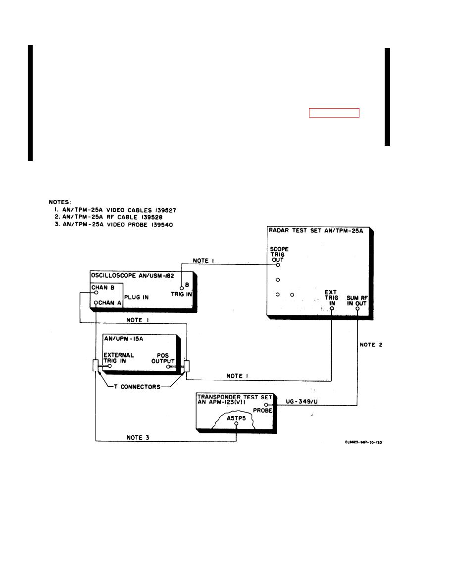
Figure 7.1-1. Depot system timing setup using AN/TPM-25A. |
|
||
| ||||||||||
|
|
 TM 11-6625-667-45/NAVAIR 16-30APM123-2/TO 33A1-3-367-22
Control
Position
g. Adjust the AN/UPM-15A PULSE DELAY
M4 JAMMING
0
as required to position the delayed pulse ap-
PRT SEL( SEC)
Immaterial
proximately .5 ms before the trailing edge of the
TRIG SEL INT DCD/EXT
EXT
prf pulse. Continue adjustment as necessary until
SIG GEN FUNCTION
FIXED
the transponder test set ACCEPT lamp is on.
FREQ
NORM INTERLEAVE
NORM
h. Without disturbing any equipment setting,
SUM ATTEN
-6dB
shut all equipment off and connect the test
MEASUREMENT FUNCTION SEL
PWR
equipment as shown in figure 7.1-2, depot
e. Turn on the AN/TPM-25A, AN/UPM-15A,
overhaul standards basic test.
AN/USM-182, and the transponder test set.
i. Turn all equipment on and note that trans-
f. On the AN/USM-182, observe the positive
ponder test set ACCEPT lamp is on.
going 2.17 ms prf pulse from A5TP5 and the
delayed prf pulse from the AN/UPM-15A.
Figure 7.1-1. Depot system timing setup using AN/TPM-25A.
7.1-2
Change 5
|
|
Privacy Statement - Press Release - Copyright Information. - Contact Us |
