 |
|||
|
|
|||
|
|
|||
| ||||||||||
|
|
 TM 11-6625-667-45/NAVAIR 16-30APM123-2/TO 33A1-3-367-22
h. Adjust the AN/UPM-98 SUB PULSE POS
control to the center (0) position, and repeat the
procedures in b through e above.
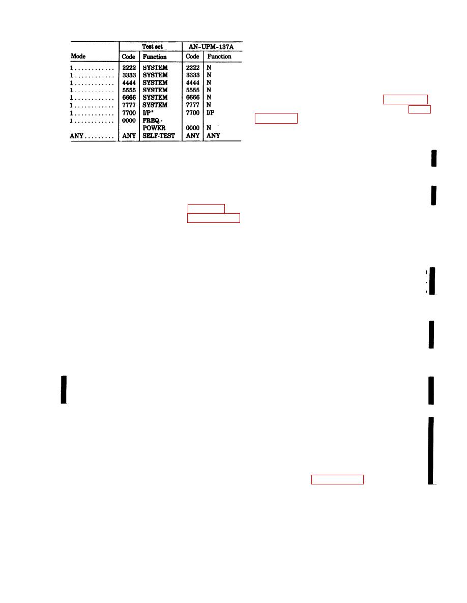
7-10.1. Reply Evaluator Test Using
AN/UPM-137A
Connect the equipment as shown in figure 7-1.1.
Set and adjust the controls as described in para-
a. Set ME-26B/U SELECTOR switch to (+) and
RANGE switch to 10V. Connect common lead to
A13TP2 (ground) and dc probe to A12TP2.
*Set AN/UPM-137A SIS generator SIF 2 CODE R-CODE
switches to 7700 and adjust SIF 2 CODER-TRIG DELAY ADJ
b. Set AN/UPM-137A SIS generator SIF 1
control unit first pulse of SIF 2 train coincides with I/P pulse of
CODER-code (A, B, C, D) switches to 7777.
SIF 1 train.
c. Set test set CODE switches to 7777.
CODER-SUBST PULSE POSN control completely
7-10. Reply Evaluator Test
clockwise.
e. Adjust ME-26B/U ZERO ADJ for zero meter
Connect the equipment as shown in figure 7-1, and
indication.
adjust the controls as described in paragraph 7-3.
Multimeter ME-26B/U will also be used; instruc-
CODER-SUBST PULSE POSN control to 0. Note
tions are provided in a through h below.
ME-26B/U indication.
a. Set the ME-26B/U SELECTOR switch to (+)
and the RANGE switch to 10V. Connect the dc
probe to test point A12TP2 (module A12) and com-
CODER-SUBST PULSE POSN control, in either di-
rection, until dc voltage indicated ME-26B/U is 80
mon lead to test point A13TP2 (module A13).
b. Set the AN/UPM-98 controls to 7777. Adjust
percent of that noted in f. Test set ACCEPT in-
the ME-26B/U ZERO control to zero its indication.
dicator should be lighted. If not lighted, proceed to
c. Set the AN/UPM-98 CODE switches to 7767.
step i.
Note the ME-26B/U voltage indication.
d. Adjust the AN/UPM-98 SUB PULSE POS
CODER-SUBST PULSE POSN control, in either di-
rection, until dc voltage indicated on ME-26B/U is
control in the negative (-) direction until the
ME-26B/U voltage indication is 50 percent of that
50 percent of that noted in f. Test set REJECT in-
noted in c above. The test set REJECT indicator
dicator should be lighted. If not lighted, proceed to i
should light. If it is not lighted, proceed with f
below.
below.
CODER-SUBST PULSE POSN control, in either di-
e. Adjust the AN/UPM-98 SUB PULSE POS
rection, until dc voltage indicated on ME-26B/U is
control in the positive (+) direction until the
65 percent of that noted in f. Adjust control
ME-26B/U voltage indication is 20 percent of that
noted in c above, Reset the AN/UPM-98 code
A12R19 until test set ACCEPT and REJECT in-
dicators light alternately. Repeat g and h above.
switches to 7777. The test set ACCEPT indicator
should light. If it is not lighted, proceed with f be-
7-11 through 7-13. Transmitter Fre-
low.
quency, Power Out-put, and Pulse
f. Adjust the AN/UPM-98 SUB PULSE POS con-
Characteristic Tests.(Deleted)
trol in the negative (-) direction until the
ME-26B/U voltage indication is 65 percent of that
NOTE
To perform the frequency, power output,
noted in c above.
and pulse characteristic test, perform the
g. Adjust control A12R19 until the test set AC-
procedures in paragraph 3-4.
CEPT and REJECT indicators glow alternately.
Change 4
7-9
|
|
Privacy Statement - Press Release - Copyright Information. - Contact Us |
