 |
|||
|
|
|||
|
Page Title:
Read Delay, Error Detector, and Function (Controls) Test |
|
||
| ||||||||||
|
|
 TM 11-6625-667-45/NAVAIR 16-30APM123-2/TO 33A1-367-22
C4 . . . . . . . . . . . . . . A7R5
B4 . . . . . . . . . . . . . A7R11
A4 . . . . . . . . . . . . . . A7R6
F2 . . . . . . . . . . . . . A7R13
B1 . . . . . . . . . . . . . . A7R7
e. Set AN/UPM-137 SIS generator SIF 1
CODER-FUNCTIONAL SEL switch to I/P.
f. Set test set FUNCTION switch to I/P and
MODE switch to 2.
g. Repeat b and c above for I/P pulses and adjust
A7R14, if necessary, to center pulses.
7-9 Read Delay, Error Detector, and
Function (Controls) Test
Connect the equipment as shown in figure 7-1. Set
and adjust the controls as described in paragraph
a. Disconnect the oscilloscope CHANNEL A
cable from test point A11TP1 and connect the cable
i. Set the test set FUNCTION control to SELF
to test point A1OTP6 (module A10).
TEST. The ACCEPT indicator should light.
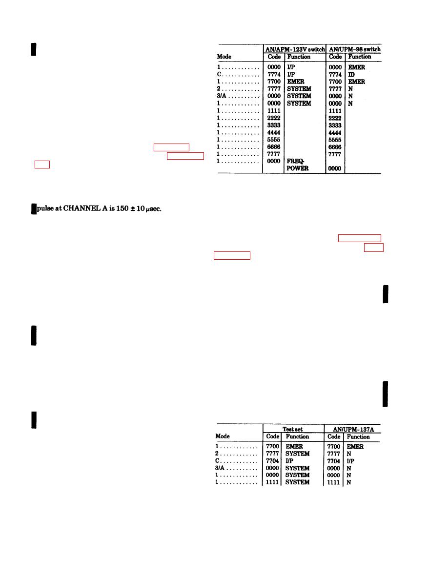
b. Measure to make sure that the width of the
7-9.1. Read Delay, Error Detector, and
Function (Controls) Test Using
from test point A10TP6, and connect the cable to
AN/UPM-137A
test point A11TP3.
Connect the equipment as shown in figure 7-1.1.
d. Set the oscilloscope HORIZONTAL DISPLAY
Set and adjust the controls as described in para-
control to B INTENSIFIED BY A, TIME BASE A
TIME/CM control to 0.1 sec and TIME BASE B
a. Connect AN/UPM-137A oscilloscope VERTI-
TIME/CM control to 0.2 sec.
CAL-CHAN A-VIDEO IN jack to test set test point
e. Adjust the DELAY TIME MULTIPLIER
A10TP6.
control until the pulse at the oscilloscope
b. Measure width of pulse display on CHAN A. It
CHANNEL A is intensified.
should be 150 10 sec.
f. Set the HORIZONTAL DISPLAY control to A
c. Connect AN/UPM-137A oscilloscope VERTI-
DEL'D BY B.
CAL-CHAN A-VIDEO IN jack to test set test point
g. Measure to make sure that the width of the
A11TP3.
pulse at oscilloscope CHANNEL A is 0.35 0.01
d. Measure width of pulse displayed on CHAN A.
sec.
It should be 0.35 0.01 sec.
NOTE
If necessary, adjust control A11R30 to ob-
NOTE
tain the required performance standard.
If necessary, adjust control A11R30 to ob-
tain the required performance standard.
controls for each mode as indicated below. Set
AN/UPM-137A SIS generator MIXED VIDEO-
MIXED VID SEL switch to SIF 1,2. The test set
h. Set the test set and AN/UPM-98 controls for
ACCEPT indicator should light for each setting.
each mode as indicated below. The test set ACCEPT
indicator should light for each of the modes.
SWEEP DELAY range dial on the AN/UPM-98
should be set to 1 to 11 for Modes 1, 2, and 3A.
Adjust SWEEP DELAY-COARSE or FINE control
to obtain acceptance. SWEEP DELAY range dial
should be on 5-50 for MODE C. Adjust SWEEP
DELAY-COARSE or FINE control to obtain accep-
tance.
7-8
Change 4
|
|
Privacy Statement - Press Release - Copyright Information. - Contact Us |
