 |
|||
|
|
|||
|
Page Title:
Section II. TROUBLESHOOTING PROCEDURES |
|
||
| ||||||||||
|
|
 TM 11-6625-542-14-1
Section II. TROUBLESHOOTING PROCEDURES
6-4. Preliminary Setup
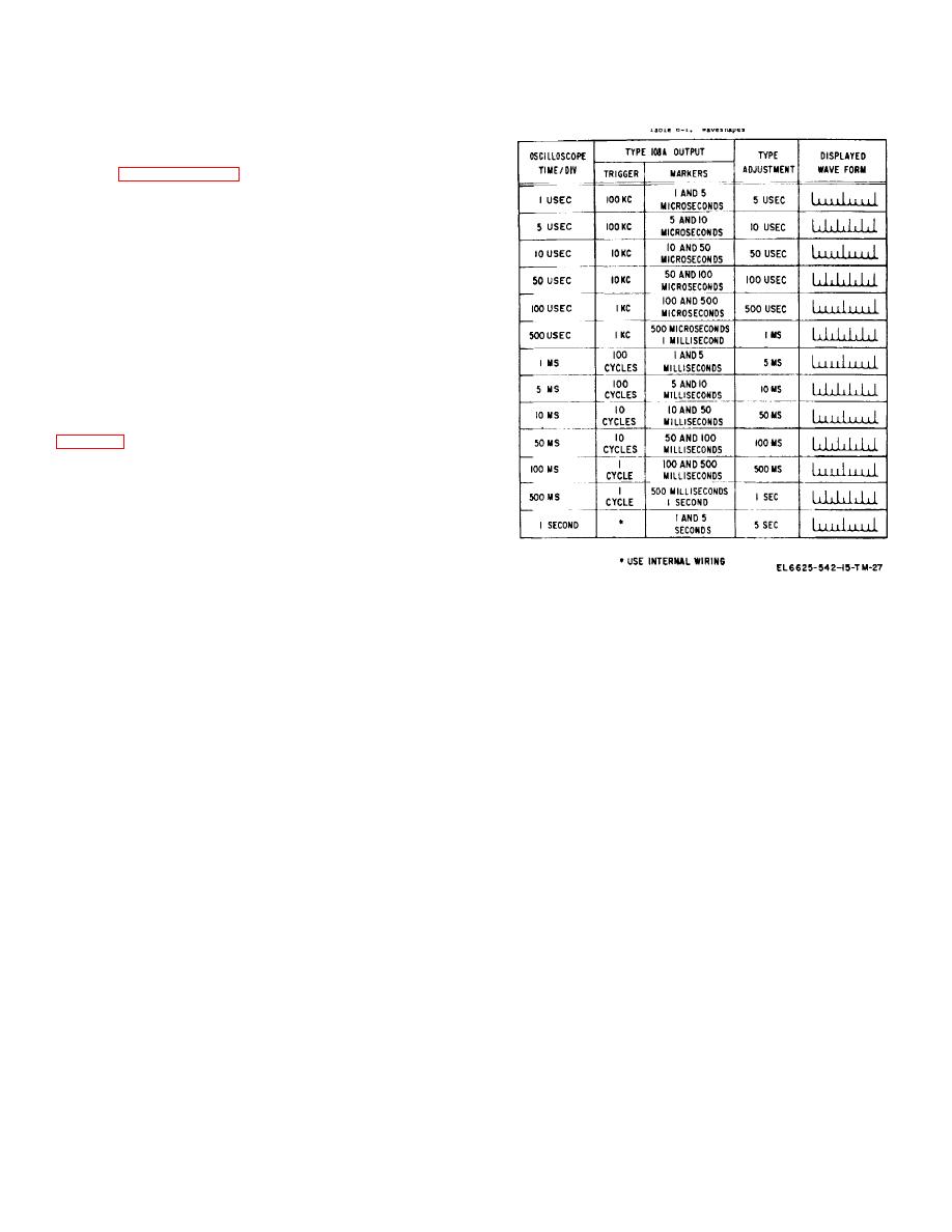
Table 6-1. Waveshapes
a. Determine power source to be used and
connect power cable to rear of the AN/USM-108A and to
power source. If other than 117 vac power is to be used,
refer to paragraph 2-4 for rewiring of the power
b. Set POWER ON switch to ON and check to
see that POWER ON indicator and CRYSTAL HEATER
indicator illuminate.
c. Allow equipment to warmup for a minimum of
15 minutes prior to testing.
CAUTION
This is a precision electronic test instrument. As
such, it includes factory adjusted controls and
specially processed vacuum tube. Unnecessary
tube replacement may degrade the performance
of the unit. When testing vacuum tubes, replace
all good tubes in their original sockets.
6-5. Operational Test
a. Microseconds Circuits.
(1) Connect oscilloscope to MARKER OUT
connector (refer to section IV for test equipment setup).
(2) Check to see that proper waveshapes and
time marks are obtained when MICROSECONDS
pushbuttons are depressed.
b. Milliseconds Circuits. Connect oscilloscope to
MARKER OUT connector and check to see that proper
waveshapes and time marks are obtained when
6-6. Sectionalization Testing
MILLISECONDS pushbuttons are depressed.
The following procedure describes methods by which
c. Second Circuits.
Connect oscilloscope to
troubles may be traced to a particular section. When
MARKER OUT connector and check to see that proper
troubleshooting the AN/USM-108A, investigate the power
waveshapes and time marks are obtained when
supply section first, because all other sections are
SECONDS pushbuttons are depressed.
dependent upon it.
d. Trigger Rate Circuits. Connect oscilloscope to
a. Power Supply.
TRIGGER OUT connector and check to see that proper
(1) Check to see that ac power is connected.
waveshapes and time marks are obtained when
(2) With POWER ON switch in the ON
TRIGGER RATE pushbuttons are depressed.
position, indicator lamp should be lighted and cooling fan
operating. Check fuse F101 if necessary.
(3) Take a voltage measurement check at the
6-2
|
|
Privacy Statement - Press Release - Copyright Information. - Contact Us |
