 |
|||
|
|
|||
|
Page Title:
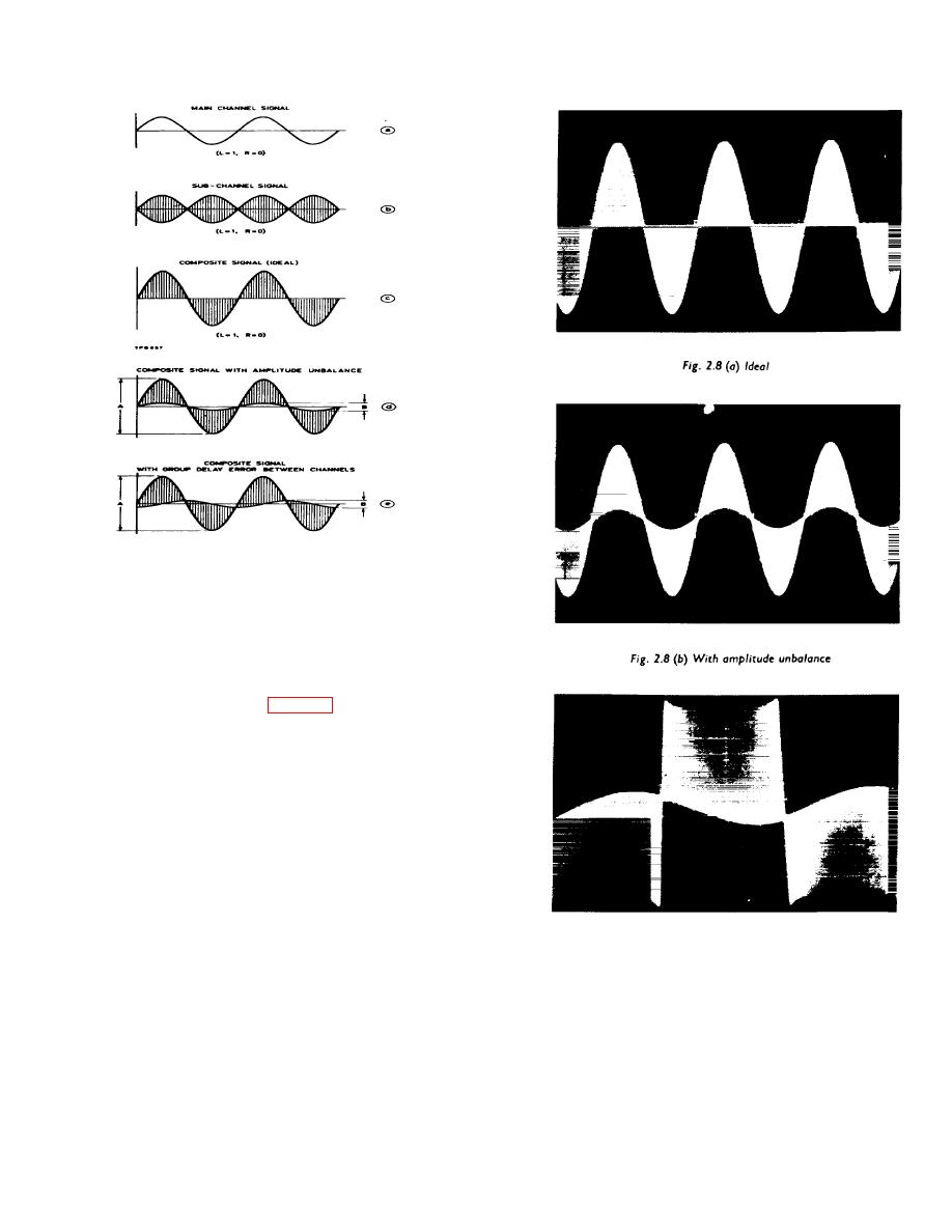
Fig 2-8. Oscillograms of composite signal |
|
||
| ||||||||||
|
|
 TM 11-662 5-3014-14
Fig. 2-7. Derivation of composite
stereo signal showing unbalance and
phase shift errors
The test arrangement for measuring channel
separation is as illustrated in Fig. 2-6, except that the
wave analyser is now replaced by an oscilloscope, and
the procedure is as follows :
(1)
Set up the equipment and modulation meter is
already described for distortion measurements.
Fig. 2-8.(c). With phase shift error
Fig 2-8. Oscillograms of composite signal
2-13
|
|
Privacy Statement - Press Release - Copyright Information. - Contact Us |
