 |
|||
|
|
|||
|
Page Title:
Figure 13. Simplified selector switch diagram. |
|
||
| ||||||||||
|
|
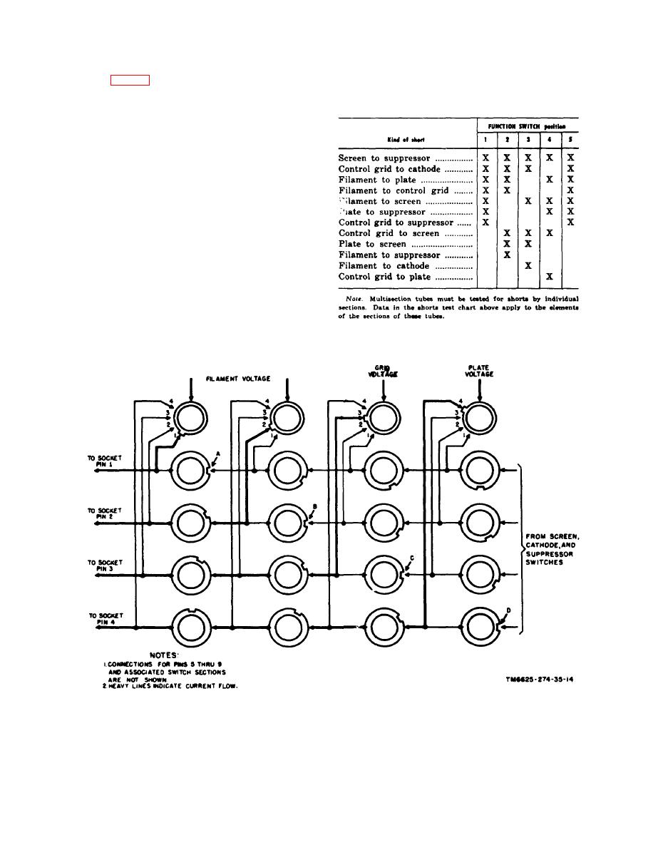 element shorts within a tube and the positions
S109 (fig. 14) shows the shorts test section of
o f the FUNCTION SWITCH in which the
the switch in position 1. In this position, the
SHORTS lamp will glow for a particular short:
cathode, the filament, and the suppressor grid
of the tube under test are in contact with seg-
ment Y; the screen grid, the plate, and the
control grid are in contact with segment Z.
Any shorted condition between an element on
segment Y and elements on segment Z com-
pletes the circuit between C102 and E101, and
SHORTS lamp E101 will glow. Rotation of . .
s w i t c h from position 2 through position 5
changes the grouping of the elements on the
two segments. Different types of shorts will
cause the neon lamp to glow on different posi-
tions of the switch; that is, a screen-to-suppres-
sor short will cause the lamp to glow in all five
positions while a control grid-to-plate short
will cause a glow only on position 4. The fol-
lowing chart shows the various possible inter-
18
|
|
Privacy Statement - Press Release - Copyright Information. - Contact Us |
