 |
|||
|
|
|||
|
Page Title:
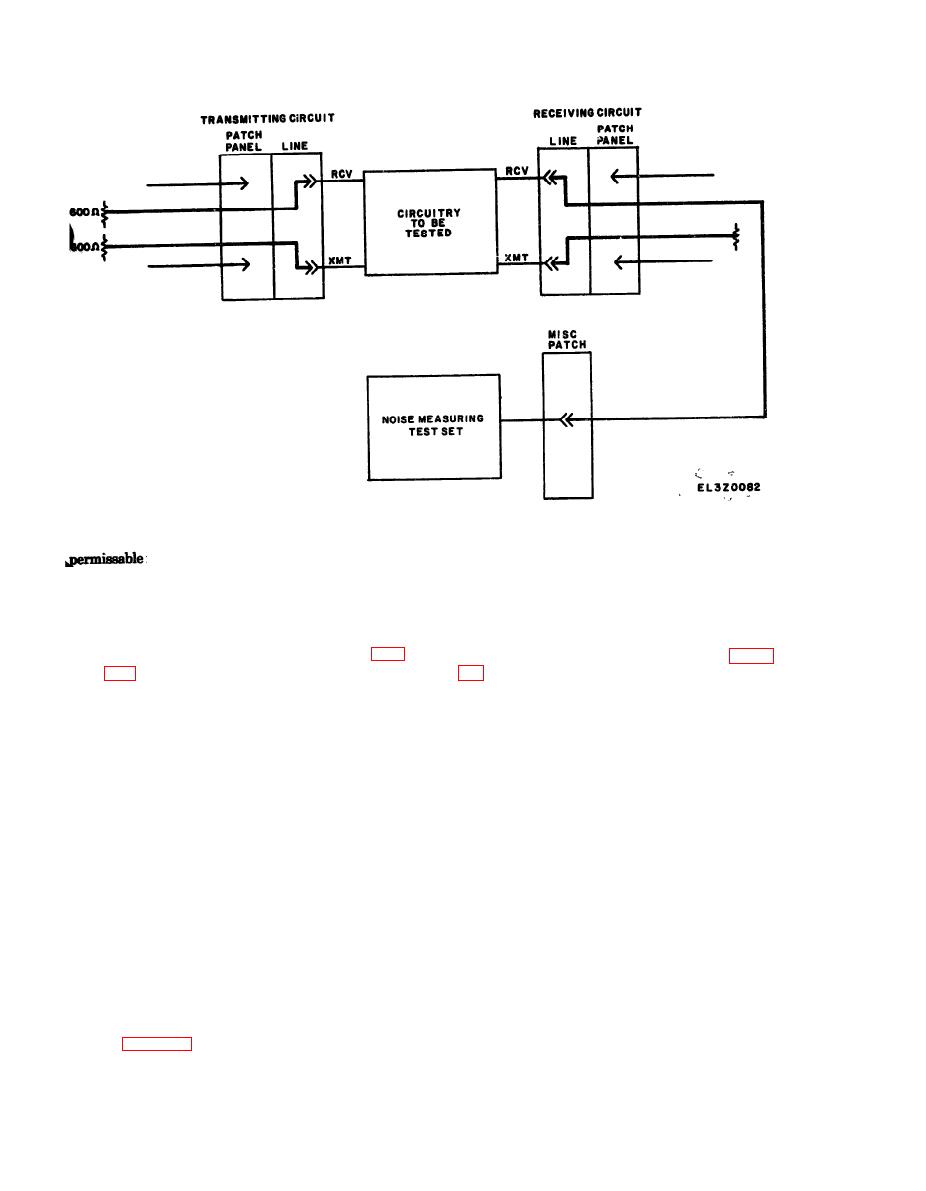
Figure 6-1. Idle channel (residual) noise teat. |
|
||
| ||||||||||
|
|
 TM 11-5895-1012-10
as follows:
from 1000 Hz if - 2 + 6 db.
(a) Transmit and receive reference.
d. In-Station Test. h-station testing is accom-
(b) Signal level of - 10 db.
plished in the same manner as station-to-station test-
(c) Carrier frequency of 2000 Hz.
ing except the local station acts as both transmitter
(d) Modulation frequency of 25 Hz.
and receiver.
(2) Receiving Circuit. If the local station is to act
as receiver, prepare the receiving circuit shown in fig-
ure 6-3 and set the envelope delay test set as follows:
(a) Receive-return reference.
a. Purpose. This test will measure circuit delay
(6) Carrier frequency of 2000 Hz.
distortion of circuits between stations or within a
(c) Modulation frequency of 25 Hz.
station and determine compliance of circuits with the
(3) Procedure. With the transmitting station
standard operating requirements. Circuit delay distor-
envelope delay test set set for the reference frequency
tion is the distortion caused by differing amounts of
of 2000 Hz, record the delay indicated on the envelope
delay for each of the various frequencies comprising
delay test set. The transmitting station will then set
the intelligence carrying signal. This is tested by trans-
the envelope delay test set for each of the frequencies.
mitting several narrow band modulation envelopes
indicated in table 6-1. As each frequency is obtained,
and measuring the difference between the longest en-
measure the delay and calculate the difference be-
velope delay and the shortest envelope delay. This dif-
tween that delay and the delay measured at the refer-
ference is called the envelope delay distortion.
ence frequency of 2000 Hx. This difference may be
b. Test Equipment. Two envelope delay test sets are
either positive (more delay than was measured at 2000
required if the teat is to be conducted within a station.
Hz) or negative (less delay than was measured at 2000
One envelope delay test set is required for each station
the test is to be conducted between two stations.
Hz).
(4) Performance Standard. The maximum
c. Station-to-Station Test. Contact distant station
deviation permissible from the reference frequency of
and arrange for one station to act as transmitter and
2000 Hz is indicated in table 6-1.
one as receiver. Perform the procedure below and then
d. In-Station Test. In-station testing is accom-
roles and repeat the procedure.
plished in the same manner as station to station test
(1) Transmitting Circuit. If the local station is to
ing except the local station acts as both transmitter
act as transmitter, prepare the transmitting circuit
and receiver.
shown in figure 6-3 and set the envelope delay test set
|
|
Privacy Statement - Press Release - Copyright Information. - Contact Us |
