 |
|||
|
|
|||
|
Page Title:
Section II. FUNDAMENTALS OF SOLID STATE COMPONENT CHECKOUT AND REPAIR |
|
||
| ||||||||||
|
|
 TB 9-2920-225-34-1
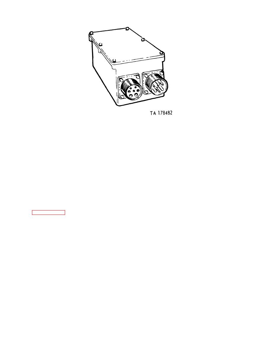
100 AMP regulator.
Figure 11.
1-4. Removal and Installation. The regulator
1-5. Major Items Affected. Because of the nu-
merous vehicles affected, a listing of the vehicles
must be removed from the vehicle for testing and
repair. The procedures given in this bulletin are
will not be supplied. Check the regulator's NSN
(2920-00-900-7993) or part number (10947439)
for bench testing and repair only. Refer to the ap-
in section IV of your vehicle's repair parts manual
propriate vehicle manual for removal and instal-
for applicability.
lation procedures for your particular vehicle.
Section II. FUNDAMENTALS OF SOLID STATE COMPONENT CHECKOUT AND REPAIR
If the voltmeter attempts to move down scale the
1-6. Introduction. a. Checkout and repair of solid
ohmmeter leads have opposite polarity, e.g., TS
state voltage regulators involves techniques dif-
352 multimeter. If necessary mark the ohmmeter
ferent from those employed with mechanical volt-
leads positive and negative for reference.
age regulators.
b. The ohmmeter readings obtained when check-
b. Before attempting checkout and repair of
ing semiconductor devices depends on the internal
solid state voltage regulators, follow the instruc-
makeup of the meter, scale used, type of transistor
tions of paragraphs 17 and 18,
and its temperature. Therefore, exact resistance
1-7. Meters. a. The type of meter used to check-
readings are seldom given. Readings are usually
out solid state components is critical and should
referred to as low resistance, which is less than 20
be limited to quality meters such as the TS-352 or
ohms; and high resistance which is more than 200
the Simpson 260 multimeters, or their equivalent.
ohms. Occasional failures may occur which can
When using an ohmmeter with unknown technical
be detected by these tests. If readings obtained are
specifications or characteristics, the following
doubtful or operation of the regulator is not
checks can be made to determine if the ohmmeter
proper, replace the transistors.
scales will cause damage to low power transistors.
1-8. DOs AND DON'Ts For Circuit Repair.
(1) Check the voltage across the ohmmeter
a. DO--When replacing solid state circuit
leads as the ranges are switched. No scale should
boards, clip the connecting wires, leaving a small
be used if the voltge exceeds 3 volts.
portion of wire with insulation to act as a refer-
(2) If the instrument is a combination volt-
ence for connecting points on the replacement
ohmmeter, the positive voltmeter lead may not
board.
be the positive ohmmeter lead. The polarity of the
b. DON'T--Attempt to interchange circuit
ohmmeter leads must be known. Polarity can be
boards between regulator models.
determined by connecting the ohmmeter to a
voltmeter. If the voltmeter moves up scale the
6040 tin lead composition.
ohmmeter has the same polarity as the voltmeter.
1-2
|
|
Privacy Statement - Press Release - Copyright Information. - Contact Us |
